Wireless Car Karaoke System
Wireless Car Karaoke System. David Wu, Kaoru Naganuma, Eric Lindberg ECE 445 Group 15 TA: Tony Mangognia. Our Vision. To create a device to allow passengers to enjoy karaoke entertainment while in a car. Objectives.

Wireless Car Karaoke System
E N D
Presentation Transcript
Wireless Car Karaoke System David Wu, Kaoru Naganuma, Eric Lindberg ECE 445 Group 15 TA: Tony Mangognia
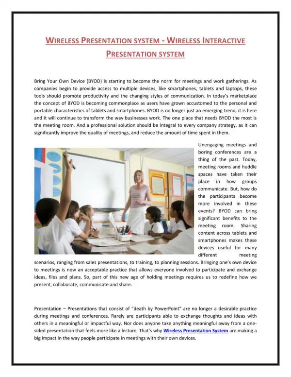
Our Vision • To create a device to allow passengers to enjoy karaoke entertainment while in a car.
Objectives • Construct a Wireless Remote to control the device through user input (Play, Pause, Forward, Back) • Play chosen song through car stereo system • Display Synchronized Lyrics • Allow user to sing along with a Microphone
ECE445 Demo Block Diagram • Remote Block Diagram
ECE445 Demo Block Diagram • System Console Block Diagram
ECE445 Demo Block Diagram • Lyrics Circuit Block Diagram
ECE445 Demo Block Diagram • Microphone Block Diagram
FPGA SD Card Music Player • Used Altera DE2 Board to playback .wav files from an SD card • FPGA coded to read FAT16, 512 byte cluster size SD cards • 16-bit .wav files read by the FPGA read 512 bytes at a time. • Output to 1/8” audio jack located on DE2 Board
1/8” Audio Output Jack SD Card Reader Seconds Counter FPGA Circuit
High-Level Coding Flowchart 80 Byte Handshake/Acknowledge Protocol Read 512 Bytes from SD card Store into Size 512 Char Buffer Array Output to .wav Decoder Output to 1/8” Audio Jack If !EndofFile
Remote System Overview • Controlled by PIC16F877A microcontrollers • Wireless transmission with LINX TX and RX chips • LCD user display w/ push button inputs
Transmitter Circuit • PIC16F877A microcontroller • 2x16 LCD w/ 4 push buttons • LINX TXM-900-HP3 • 9V Battery
Transmitter – PIC Microcontroller • Reads user input via push buttons • Encodes user input • Send encoded data with LINX TXM-900-HP3 wireless transmitter chip • Updates LCD with user selection
Transmitter – LCD • Displays user selection • Push buttons for user input
Transmitter – LCD Driver • Custom LCD driver for interfacing with PIC • CCS LCD driver too restrictive • Custom driver allows any port mapping • Not able to use fast I/O due to custom mapping
Transmitter – LCD Push Buttons • Active low buttons • Use PNP transistor as switch • Button presses read by input port of PIC
Transmitter – LINX TXM • Operate in parallel mode • RS232 Protocol • Operates at 915.37 MHz • 9600 Baud Rate
Receiver Circuit • PIC16F877A microcontroller • LINX RXM-900-HP3 • MAX232A • Dsub-9 Connector
Receiver – PIC Microcontroller • Receives data from LINX receiver • Decode data and update LCD display • Send data to MAX232 and Dsub-9 connector
Receiver – LINX RXM • Receives data over RS232 protocol • Operates at 915.37 MHz • 9600 Baud Rate
Receiver – MAX232 and Dsub-9 • Data from PIC is processed through MAX232 • MAX232 -> Dsub-9 via TX Pin 2 • Dsub-9 -> FPGA via RS232 protocol
Remote Circuit Tests • Range Test • Accuracy Test • Hyperterminal Test
Remote Range and Accuracy Tests Average accuracy = 91.2%
Remote Range and Accuracy Tests Average accuracy = 95.0%
Remote Hyperterminal Test • Hyperterminal use to test Dsub-9 and RS232 connection • If a button is press a string should appear in the Hyperterminal window • Settings: Port = COM1, Baud = 9600, Data Bits = 8, Parity = None, Stop Bits = 1, Flow Control = None
Audio Amplification Overview Three Main Parts: LM1875 Audio Power Amps LM747 Op Amps provides pre-amplification Amps powered by LT1070 switching boost converters
Board View Power Supply Amplifier Preamp
Power Supply Operates by switching on and off at 40kHz charging and discharging the inductor Voltage is then filtered through large capacitor Output Power 15-20W
Full Power Supply Circuit MRB1045 R1 R2
Design of Power Supply Resistors R1 and R2 used to set the output voltage of the circuit Chose 150uH, 3A inductor as compromise between cost, inductance, and current rating Floating ground provides positive and negative voltages
Power Supply Output Vcc = 25V ΔV=656mV f=4kHz and f=40kHz Input: 12V DC
Preamp Op amp buffers between input audio signal and audio power amplifier Allows for adjustment of volume via two pots
Audio Power Amplifier Two non inverting amplifiers, one complete circuit for each channel Variable gain 1-20, adjustable via pot Input capacitor removes DC part of signal
Diagram of Amplification Stage HP Filter: fc=2.2Hz High Freq. Noise Filter
Design of Amplifiers • Preamp Stage • Op amp has minus terminal connected to output to implement voltage follower • Voltage divider is used to attenuate incoming signal • Power Amp Stage • Basic non inverting amplifier configuration • Filters reduce noise and eliminate DC input, used ones recommended in datasheet
Frequency Response of Amplifier Flat passband No significant phase shift in passband Used oscilloscope to measure data points
Current Problems • Noise / Signal Distortion • EM Interference • Grounding Issues • Ground Loops • Large signals from the amplifier output can affect the small signals of the input • Optimized PCB should fix most of these issues • Heat • Amplifier shuts down when it gets too hot • The power amplifiers and the LT1070 both have sophisticated thermal protection circuits • Better heat sinking, fan to provide airflow
Lyrics Circuit Overview • Lyrics Coded Directly into PIC16F877A • Lyrics appear on 2x16 Character LCD panel synchronized using timing delays • Song: Mrs. Robinson – Simon and Garfunkel
Lyrics Circuit • PIC16F877A • 2x16 LCD Panel • Can be powered by 12 V Car Battery
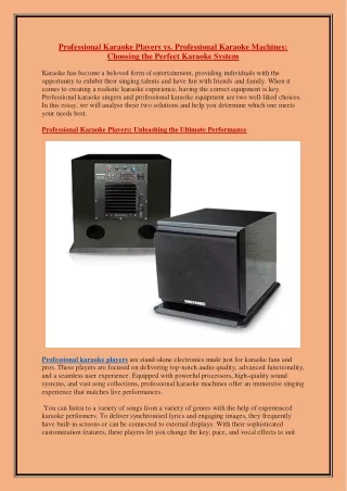
Microphone • Wireless Microphone is connected directly to a second set of speakers • PYLE-PRO PDWM 100
System Circuit without Remote Music Output Amplifier Circuit Microphone Output Lyrics Display Microphone Receiver FPGA SD Music Player
Current Challenges 1) Music Player cannot SKIP, PAUSE, BACK, PLAY on commandExplanation:Could not implement endfile command successfully in our code in order to skip, pause, etc. Ran out of time to debug these features Possible Solution: Spend more time debugging features that use the endfile command. Approximate time needed: 1-2 weeks 2) Remote is not connected to FPGA through RS232/Dsub9Explanation:Could not communicate successfully through the RS232 on the FPGA. Ran out of time to debug this feature Possible Solution:Spend more time debugging communication to the FPGA through the RS232 portApproximate time needed: 1-2 weeks
Current Challenges 3) Cannot read synchronized lyrics from SD card Explanation: PIC16F877A does not have enough RAM to handle a 512 byte character array needed to interface with a FAT16 512 byte cluster size SD card. (Smallest standard size) Possible Solution: Use and alternate microcontroller, such as the PIC18F452, which has more RAM available Approximate time needed: 1 week 4) Cannot display to Car LCD ScreenExplanation: PIC16F877A does not have enough RAM to handle needed video bitrate Possible Solution: Research what microprocessor will allow us to handle the needed video bitrate. TI Multimedia chips are commonly used for this feature.
The Next Step • Fix Problems 1-4 in order to achieve a device closer to our vision • Implement a Mixer to mix the Microphone Signal and the Music Signal in order to output together • Add more user-friendly features to make the device more appealing and accessible • Create connectors so that the device works in various cars rather than one single type of car (Marketing)