Download
1 / 112
1.12k likes | 1.15k Views
This seminar discusses the design, commissioning, and luminosity upgrade of the BEPC-II storage rings, including the problems faced during luminosity commissioning and possible upgrades for increased luminosity.

E N D
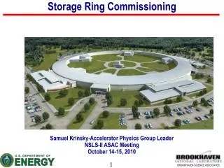
Design, commissioning and luminosity upgrade of the BEPC-II storage rings Qing Qin (秦庆) For the Accelerator Physics Group IHEP, Beijing 100049, P.R. China Seminar at LNF
Contents • Brief introduction on the BEPC-II • Design of the BEPC-II rings • Commissioning of the SR and collision modes • Problems met during luminosity commissioning • Operation for users • Possible upgrades for luminosity • Summary Seminar at LNF
1. Brief introduction on the BEPC-II • BEPC-II — An upgrade project of the BEPC — A two-ring factory-like machine — Deliver beams to both HEP & SR Seminar at LNF
Milestones of BEPC-II • July 1997, Proposal on BEPC upgrades (single-ring) • July 2000, Official approval from government • Jan. 2001, Double-ring scheme proposed • Jan. 2004, Construction started • Nov. 2004, Linac finished upgrade and delivered beam • July, 2005, BEPC stopped, ring disassembly started • Nov. 2006, Ring commissioning started • July 2008, First hadron event collected in BES-III • May 2009, Luminosity reached 3.31032cm-2s-1 Seminar at LNF
Single-ring scheme, pretzel orbits Seminar at LNF
Double-ring scheme Seminar at LNF
Goals of the BEPC-II • Collision Mode • Beam energy range 1-2.1 GeV • Optimized beam energy 1.89 GeV • Luminosity 3-101032 cm-2s-1 @1.89 GeV • Full energy injection 1-1.89 GeV • SR Mode • Beam energy 2.5 GeV • Beam current 250 mA • Keep the original beam lines of BEPC to save budget Seminar at LNF
Strategy of luminosity upgrade DR: multy-bunch kbmax~400,kb=1 93 Choose large ex & optimum param.: Ib=9.8mA, xy=0.04 Reduce impedance +SC RF sz=5cm <1.5cm Micro-b:by*=5cm 1.5 cm SC insertion quads (LBEPCII/ LBEPC)D.R.=(5.5/1.5) 93 9.8/35=96 LBEPC=1.010 31 cm-2s-1 LBEPCII =110 33 cm-2s-1 Seminar at LNF
2. Design of the BEPC-II rings • Beam-beam simulation and working points Strong – weak Strong – strong Seminar at LNF
Simulation and Tune scan Seminar at LNF
Geometry of the IR and RF regions Geometry of Interaction Region Seminar at LNF Geometry of RF region
ISPB SCQ IP Interaction region for the collision mode SCB SCB Seminar at LNF Interaction region for the dedicated SR mode
Lattice design of the storage rings • Design philosophy • Use the existing BEPC tunnel • Keep the BEPC SR ports for beam lines • Use as more BEPC magnets as possible • Keep the BEPC injection scheme • Fit 500MHz RF system, and the two-bunch injection scheme in the future • Match the luminosity and other requirements from hardware Seminar at LNF
Design Parameters of Ring (Col. Mode) Seminar at LNF
Design Parameters of Ring (SR Mode) Seminar at LNF
Parameters of on-line lattice (collision mode) Seminar at LNF
Non-linearity • Sextupole optimization • Dynamic aperture opti. Seminar at LNF
Dynamic aperture Off-momentum particles with all kinds magnetic errors (20 seeds, 26 off-momentum particles) Average Dynap Minimum Dynap Injection aperture Injection aperture Seminar at LNF
Detector solenoid compensation AS1 – 3 are connected in series, but AS2 and AS3 have trims Seminar at LNF
Impedance and beam instabilities Impedance budget Seminar at LNF
Longitudinal wake field of the ring Seminar at LNF
Bunch lengthening w/ TiN coating w/o TiN coating Simulation on ECI Seminar at LNF
Growth time of coupled-bunch instabilities Seminar at LNF
3. Commissioning of the SR and collision modes 2006 Oct. Installation completed with NIM-IR 2006 Nov 18 First beam stored 2007 Mar 26 First collision 2007 May 14 Luminosity reached that of BEPC 2007 Oct. Installation completed with SIM-IR 2007 Oct. 24 First beam stored 2007 Nov. 18 First collision 2008 Jan. 29 Luminosity >11032cm-2s-1 2008 June. Installation completed with BESIII in the IR July 19, 2008 First event detected with BESIII April 8, 2009 Luminosity reached 2.3 1032cm-2s-1 May19, 2009 Luminosity reached 3.3 1032cm-2s-1 Phase 1 Phase 2 Phase 3 Seminar at LNF
Beam optics realization With LOCO (Linear Optics from Closed Orbits), the parameters of a computing model can be adjusted until the model response matrix fits the measured response matrix well enough. Determine the errors by, • ΔK q — error of quadrupole strength • ΔGi — error of BPM gain • Δθj — error of corrector strength • Δδj — energy shift when horizontal corrector strength change Seminar at LNF
Beam optics analysis Measured response matrix Difference between the measured and the model response matrices after fitting with LOCO Seminar at LNF
Beam optics analysis • Distribution of residual differences between measured and fitted response matrices, normalized to the noise level of the individual BPMs • Width of the distribution ~1 • The fitting in LOCO converged to the noise level of BPMs. Seminar at LNF
Beam optics analysis • The change of quadrupole strengths to restore the optics is described by using the amplitude fudge factor. K0 : design strengthK: optimized strength • Most of the quad’s fudge factors are within 1% • Some quads, such as Q15 and Q02, AF ~ 6%. Reason: same polarity with the neighbour quads. • Problems found from the abnormal AF s: • shortcut of magnet poles: R1OQ16 and R2OS7 • grounding problem of R3OQ04 • fitting method for the SCQs @ IP. Seminar at LNF
BER BPR Seminar at LNF
Results The comparison of measured and design Beta function after optics correction Seminar at LNF
After the optics corrections with response matrix, measured tunes are close to the nominal values. Seminar at LNF
Understanding the fudge factors • Large fudge factors --- hardware problems: magnet, PS, database, model of special magnet, etc. • Small fudge factors --- interaction between quad and sext in arcs, fringe field effect of dipoles and quads. • Aim --- get fudge factors as small as possible, KK0 • Experiment performed at BSR, no wiggler and no optics correction, • nominal tunes (7.28,5.38) Seminar at LNF
Orbit correction with response matrix Seminar at LNF
Bad BPM Seminar at LNF
Chromaticity x ~ 1.6, x0 = 1.0 Seminar at LNF
Chromaticity measured at the phase 1 of commissioning Seminar at LNF
Optimized RF frequency Seminar at LNF
Transverse coupling • Adjusted with the vertical bump in sextupoles • Measured with tune split method BER: ~ 1.24% BPR: ~ 1.02% Seminar at LNF
Changing vertical orbit to get C12, adjusting coupling BPR BER Y=790 Y=945 Seminar at LNF
Beam energy spread • Measured from the control of quantum lifetime Seminar at LNF
BER BPR Seminar at LNF
With these basic work on the beam performance, the luminosity reached 11031cm-2s-1 in phase 1 commissioning at the beginning of 2007, without SIM or SC. detector. Seminar at LNF
Time delay scan Amplitude scan Beam injection Set the right timing and amplitude of the two kickers => reduce the residual orbit oscillation of stored beams during injection Fixed • After optimization with one bunch, the residual orbit oscillation of all the other bunches during injection reduced to around 0.1mm/0.1x. • Injection on collision possible. =>For timing: fix k1, scan k2 ; do in turn for k2 =>For amp: fix k1 or k2 amp, scan the other Seminar at LNF 45
Result of multi-bunch injection Seminar at LNF
Impedance and instability issues Bunch lengthening • Bunch length in BER/BPR measured with streak camera. • Single bunch stored in BER/BPR, respectively, in bunch length measurement. • Keep Vrf fixed, measure the bunch length vs. bunch current. Seminar at LNF
BPR Lave= 118nH |Z/n|0 = 0.94 Seminar at LNF
BER Lave = 32.1nH |Z/n|0 = 0.25 Seminar at LNF
Tune variation vs bunch current • Betatron tunes vary with single bunch current • Effective impedance can be got from the tune variation Seminar at LNF