Download
1 / 23
230 likes | 346 Views
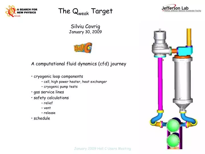
The Q weak Target Silviu Covrig January 30, 2009. A computational fluid dynamics (cfd) journey cryogenic loop components cell, high power heater, heat exchanger cryogenic pump tests gas service lines safety calculations relief vent release schedule.

E N D
The Qweak TargetSilviu CovrigJanuary 30, 2009 A computational fluid dynamics (cfd) journey cryogenic loop components cell, high power heater, heat exchanger cryogenic pump tests gas service lines safety calculations relief vent release schedule January 2009 Hall C Users Meeting
Qweak Target Parameters • beam: 1.165 GeV, 180 µA, raster 5x5 mm2, FWHM ~ 200 µm • lh2: 20 K (3.7 K sub-cooled), 35 psia (2.4 atm) @ 1 kg/s (15 l/s) • t = 2.5 g/cm2, 4 % radiator • beam heating: 2100 W in lh2, 25 W in 2x0.127 mm Al nipples • total design target power: 2500 W = beam heating + losses • density fluctuations 45 ppm@250 Hz helicity flip -> 5% increase to detector asymmetry width Qweak Target Players G. Smith and S. Covrig (Hall C – Jlab) D. Meekins (Target Group – Jlab) J. Dunne and D. Brown (Miss. State. U.) + JLab designers and engineers The highest power lh2 target in the world January 2009 Hall C Users Meeting
Computational Fluid Dynamics Software engine for cfd simulations from Fluent.Inc, used in Qweak courtesy of F. William Hersman, UNH In Qweak used for designing the cell, hph, hx check-out and a host of simulations for the target safety assessment how it works: control-volume-based technique, converts a general scalar equation for into a scalar equation to solve numerically which is linearized into an algebraic equation the equations from all cells form a system of linear algebraic equations that are solved Can simulate both steady-state and time-dependent cases January 2009 Hall C Users Meeting
CFD Design Process for the Cell Simulations run in steady-state Conditions: lh2, beam in nominal conditions, beam heating sourced as uniform power density in both lh2 and Al windows (typically 2.4e8 W/m3 in lh2, 3.9e9 W/m3 in Al), turbulence model used k-ε Requirements: minimization of both bulk heating and windows heating, in steady-state cannot estimate ⁄ on the scale of the helicity frequency • Started with a G0-type longitudinal flow cell (4 cases modeled) • Converged on a transverse flow cell (>4 cases modeled), which became the Qweak target cell NB. without cfd the Qweak target cell would have been a G0-type cell 2 liters cell January 2009 Hall C Users Meeting
Lh2 Flow and Density <vt>bv = 2.5 m/s <Δρ⁄ρ>bv = 0.74 % Δp = 0.32 psi@1 kg/s <vt>bv = 0.28 m/s <v||>bv = 3.8 m/s <Δρ⁄ρ>bv = 1.82 % Δp = 0.27 psi@1 kg/s
High Power Heater • Requirements: keep H2 liquid, fit inside 3” pipe, low Δp, 1.2 Ω total • Conditions: • LH2 in at 35 psia, 19 K, 1 kg/s (boils at 23.7 K) • coils wire NiCr-A alloy, 13AWG (0.9144 mm radius) • 2500 W heating in the bulk • g10 support with 1.5 mm radius holes for wires • Results: • found 2 models that work, 6v = 4-coil model and 8v = 2 coil model • 4-layer model delivered to Jlab from MSU (J. Dunne & D. Brown) Simulated 8 cases with fluent, narrowed down 2 models that work for us January 2009 Hall C Users Meeting
4-layer and 2-layer HPHs lh2 flow January 2009 Hall C Users Meeting
Designed by the JLab target group • 3 fin-tube coils in parallel in 3 sections, fully balanced (same pressure drop in all 3 circuits) • it is a hybrid hx, getting both 4 K (2 coils) and 15 K (1 coil) He coolant • designed for: 500 W cooling from 15 K circuit @17 g/s and 2500 W cooling from 4 K circuit @25 g/s • estimated lh2 pressure drop 0.6 psi@1 kg/s • 24 liters of lh2 Heat Exchanger 87.3 cm long, 27.3 cm diameter Cooling power design 3000 W January 2009 Hall C Users Meeting
Cryogenic Pump Assembled in-house (D. Meekins): Al turbo-charger impeller for car racing on a ¾” SS shaft of a 1HP inverter-duty, 29 Hz/ 230 V/ 2.8 A Baldor motor (max 100 Hz) Requirement: 1.5 psid@15 liters/s@20 K in lh2 January 2009 Hall C Users Meeting
LN2 Pump Tests • 1st try 10.27.08, pump fully assembled, closed loop – starts at low f, goes to 100Hz and seizes at re-start (chocked flow suspected) • 2nd try 10.29.08, pump fully assembled, open loop, seizes above 5 Hz (bearing suspected) • 3rd try 11.03.08, pump fully assembled, open loop impeller freezes at low f in LN2 during cool-down (bearing suspected) • 4th try 11.06.08, motor only, assembled in its house with one new bearing, controller overloads at low f (after settling in LN2) Diagnostics: • controller bridged to motor and power line • need new bearings • 5th try at RT in water, works like a charm Expected 1.4 psid at 5 l/s in LN2 January 2009 Hall C Users Meeting
Pump Tests Pictures Measured in H2O 1.1 psid at 10 Hz 5.4 psid at 30 Hz January 2009 Hall C Users Meeting
Gas Panel and Service Lines 6000 gal ballast capacity outside Hall C, at 66 psia RT H2 • functions: provide gases to the target loop (pumping, purging, normal running), relieve the cryogenic loop safely in a breach of vacuum, pressure buffer, pressure monitoring • bought ASME stamped MVs and RDs (for both relief and vent lines) • will use explosion proof PTs, DPT off the G0 panel • manufacturing will proceed once the pump is off the table January 2009 Hall C Users Meeting
Target Safety Nominally lh2: 54 liters (3.9 kg), 35 psia, 20 K – thermal energy in the target cold 15.5 MJ Risks: ODH (pressure system/cryogenics), flammability (fire/explosion) thermal energy from combustion 556 MJ (would cause an 18˚C increase in Hall C) There are 2 containment boundaries for lh2, the cryogenic loop and the target chamber Relief = target chamber vacuum breach, cryogenic loop intact Vent = cryogenic loop breaks, target chamber intact Release = both the loop and the chamber breach -> H2 in Hall C • two independent calculations of overpressure that concur for relief and vent • for 2” relief pipelines, mass rate of 105 g/s causes Δpmax = 14.6 psi or pmax = 81 psia • for 3.5” vent lines, mass rate of 171 g/s causes Δpmax = 7 psig • fluent time-dependent simulations for 2 different vent events and three cases of H2 release in Hall C • for 3.5” vent lines, in 3.1 sec, mass rate 210 g/s causes Δp = 13 psig (and rising), in disagreement with the calculation (the cfd simulation accounts for the time-evolution of the process, the calculation does not!) January 2009 Hall C Users Meeting
Fluent Vent Simulations Mitigate BLEVE
H2 release in Hall C • 3 cases studied, H2 escapes through a 2” diameter hole in the scattering chamber at room temperature (case 1 - hole in the bottom plate, case 2 – hole in the top plate, case 3 – hole in the side-wall) • first 20 s H2 out at 200 g/s, next 35 s H2 dispersion • 8” active/passive outlet vent on top of the dome, 8” active inlet air vent on side of the Hall C wall were considered • Hall C volume 26e3 m3, escaped H2 expands to 45 m3@RT (no ODH) • H2 flammability/deflagration range in air 4-74% by volume (sub-somic waves) • H2 detonation/explosion range in air 18-54% by volume (super-sonic waves) • two movies made for each case, RED = flammability, detonation ranges respectively • most likely safety risk event: a H2 fire, small hole could cause sonic boom (vmax through 2” hole 1350 m/s in H2) Will have to consider mitigating possible ignition sources for fire January 2009 Hall C Users Meeting
Target Schedule Pre-Installation complete design of major subsystems by Feb09 assemble it in the test lab beginning of summer09 cold He tests in the test lab summer09 (need a complete loop) safety review spring-summer09 (when design and certification ready) Installation target window 2.03.10 – 4.28.10 gas panel 2.04 alignment and survey 3.04 – 3.05 pump-out/leak check 3.10 – 3.12 safety walkthrough & as built review 4.08 – 4.14 LNeon test 4.15 – 4.19 LH2 no-beam tests 4.23 – 4.28 … January 2009 Hall C Users Meeting
Gate valve and beam line Vacuum window missing P. Degtiarenko 1 MRad/h
Motion Mechanism • vertical lifter • 24” travel, 6 positions • spare limit switches, relays and dc power supplies procured • has to be thoroughly tested in the test lab • horizontal motion • 2” travel • brake and limit switches ordered • 900, 10:1 gear box was degreased and packed with vacuum grease • the Phytron motor is the first target component controlled from the target-IOC • has to be tested in the test lab MSU logic diagram for the cryogenic loop vertical lifter using IDC-S6961 January 2009 Hall C Users Meeting
Downstream Gate Valve 16” all Aluminum, special design at $11.9k There is no thin window on the scattering chamber • Made by Vacuum Research Co. • closes on power failure • extended body • non-magnetic • material certifications provided • closing time ~5 sec • 24 VDC explosion proof solenoid • position/limit switches explosion proof for class 1, division 1, group B (H2) • has Buna O-rings, will change with metal ones