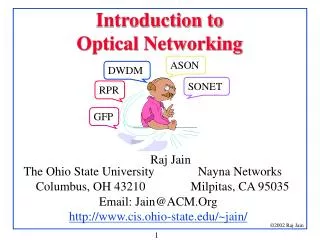
INTRODUCTION TO OPTICAL NETWORKS
INTRODUCTION TO OPTICAL NETWORKS. Presentation Overview. Why Optical Networks..?! Generations of Optical Networks The Classical Layered Hierarchy The Optical Layer Functions of Optical Layer Advantages of Layering Architectures Of Networks Access Networks: Introduction

INTRODUCTION TO OPTICAL NETWORKS
E N D
Presentation Transcript
Presentation Overview • Why Optical Networks..?! • Generations of Optical Networks • The Classical Layered Hierarchy • The Optical Layer • Functions of Optical Layer • Advantages of Layering • Architectures Of Networks • Access Networks: Introduction • Why Passive Optical Networks..?! • Passive Optical Access Network • Ethernet Passive Optical Network (EPON) • Downstream and Upstream Operation • WDM-Passive Optical Network (WDM-PON) • Ring-Based WDM-PON Architecture • Downstream and Upstream Operation
Why Optical Networks ...?? Dramatic changes in the telecommunication industry. • Need for more capacity in the network. • Tremendous growth of the Internet and the World Wide Web in terms of • number of users & the amount of time • bandwidth taken by each user – internet traffic growing rapidly. • Businesses rely on high speed networks. • Need for more bandwidth. • Deregulation of the telephone industry. • Need of providing quality of service(QoS) to carry performance sensitive applications ( real-time voice, video etc.)
Optical Networks • Definition: An Optical Network is a telecommunication network • with transmission links that are optical fibers and • with an architecture that use designed to exploit the unique features if fibers. • High performance lightwave network –involve complex combination both optical and electronic devices. • Low-cost broadband services – Internet based applications continues to increase. • The “glue” that holds the purely optical network together consists of : • optical network nodes (ONN) connecting the fibers within the network • network access stations (NAS) interfacing user terminals and other non- optical end systems to the network • Critical role : • Reducing communications costs • Promoting competition among carriers & service providers • Increasing the demand for new services
Generations of Optical Networks • First Generation: • Optics used for transmission & provide capacity • Switching & other intelligent network functions were handled by electronics • ex. SONET (synchronous optical network) • SDH ( synchronous digital hierarchy) • Second Generation: • have routing ,switching and intelligence in the optical layer • use multiplexing techniques – provide the capacity needed
The Classical Layered Hierarchy The OSI Model • Physical layer • Provides a “pipe” with a certain amount of bandwidth to the data link layer. • Data link layer • Framing • Multiplexing • Reliable transmission –acknowledgment frames • Error detection and correction • Flow control • Demultiplexing data send over the physical layer.
The Classical Layered Hierarchy • Network Layer • Performs the end-to-end routing function of taking a message at its source • And delivering it to its destination • Controls congestion • Transport Layer • Ensuring the end-to-end • In-sequence • Ensuring error-free delivery of the transmitted messages
The Classical Layered Hierarchy • Session Layer • Sessions restoration • Token management • Synchronization • Presentation Layer • Encoding data • Application Layer • Compatibility between applications
The Optical LayerLayered View of the Optical Network The architecture is composed of an underlying optical infrastructure • Physical layer • Contains optical components executing linear(transparent)operations on optical signal. • provides basic communication services to a number of independent logical networks (LNs). • LNs are residing in the Logical layer. • Contains electronic components executing nonlinear operations on electrical signal
Functions Of The Optical Layer • Multiplexes lightpaths into a single fiber. • Allows individual lightpaths to be extracted efficiently from the composite multiplex signal at the network nodes. • Incorporates sophisticated service restoration techniques. • Incorporates management techniques. • Provides lightpaths – used by SONET and IP network elements.
Advantages of Layering • Independently control and manage each logical network simplifying these functions. • Share the total resources of the physical layer among several logical network exploiting them more efficiently. • Customize each logical network to provide specialized user services improving the QoS. • Dynamically reconfigure each logical network equipment failures and changing traffic patterns. • Use both optical and electronic degrees of freedom provide flexibility, survivability, manageability and capacity for growth and change.
Architectures Of Networks • Backbone Networks • networks in the same building, in different buildings in a campus environment, or over wide areas. • exchange of information between different LANs • Metro Area Networks (MAN) • network that interconnects users with computer resources in a geographic area or region larger than that covered by even a large local area network (LAN) but smaller than the area covered by a wide area network (WAN). • Access Networks • Distributed EPON architectures • Distributed ring-based WDM-PON architectures • Converged Optical/Wireless Access Networks
Access Networks : Introduction • Access Networks • Tremendous growth in both backbone and Metro Access Network (MAN) capacity. • End users are becoming more sophisticated • Rich multimedia • Real-time services • The “Last Mile” remains a bottleneck. • Current “Last Mile” capacity has increased from 56Kb/s (dialup modem) to a few Mb/s (cable modem or digital subscriber line (DSL) connection). • Still far short of the Gigabit line speed necessary to support rich multimedia and real-time services.
End Users Central Office Access Networks … Last/First Mile
Access Networks … • Copper-based access networks will soon no longer be able to meet the ever-growing consumer demand for bandwidth. • PON-based fiber-to-the-curb/home (FTTC/FTTH) systems are considered as possible successors to current copper-based access solutions. • Two most viable architectures: • Single channel Time-Division Multiplexed PON (TDM-PON) • Multi-channel Wavelength-Division Multiplexed PON (WDM-PON)
CO CO Passive Star Coupler CO SC Why Passive Optical Networks?A natural step in access evolution Point-to-Point links PON • Minimum fiber usage/ N+1 transceivers • Path transparency • Passive network elements • Much longer distance (~20km) than DSL (~5.5 km). • Higher bandwidth due to deeper fiber penetration. • Downstream video broadcasting. Concentration Switch in the neighborhood PON ~20 km ~1 km
Multiplexing Techniques Time Division Multiplexing (TDM) : A type of multiplexing that combines data streams by assigning each stream a different time slot in a set. TDM repeatedly transmits a fixed sequence of time slots over a single transmission channel. Wavelength Division Multiplexing (WDM): A technique of sending signals of several different wavelengths of Light into the Fibersimultaneously. In fiber optic communications, wavelength-division Multiplexing (WDM) is a technology which multiplexes multiple optical carrier signals on a single Optical Fiber by using different wavelengths (colors) of Laser light to carry different signals.WDM is similar to frequency-division multiplexing (FDM).
Optical Network Terminal and Optical Network Unit • ONU (Optical Network Unit): • An Optical Network Unit (ONU) converts optical signals transmitted via fiber to electrical signals. • These electrical signals are then sent to individual subscribers. ONUs are commonly used in fiber-to-the-home (FTTH) or fiber-to-the-curb (FTTC) applications. ONT (Optical Network Terminal): • An ONT is a media converter that is installed either outside or inside your premises, during fiber installations. • The ONT converts fiber-optic light signals to copper/electric signals. • Three wavelengths of light are used between the ONT and the Optical Line Terminal : • 1310 nm voice/data transmit • 1490 nm voice/data receive • 1550 nm video receiveEach ONT is capable of delivering: • Multiple POTS (plain old telephone service) lines • Internet data • Video
Transmission between ONT and ONU Example … • Using different wavelengths for each service makes it possible to transmit high-speed Internet and video services at the same time. • The 1310nm and 1490nm bands are used for Internet transmissions on the uplink and downlink, respectively, • The 1550nm band is used for multi-channel video broadcasts. • Wavelength multiplexing is performed at the central office and a wavelength demultiplexing mechanism is provided at the customer's house.
OLT – Optical Line Terminal • OLTs are located in provider’s central switching office. • This equipment serves as the point of origination for FTTP (Fiber-to-the-Premises) transmissions coming into and out of the national provider’s network. • An OLT, is where the PON cards reside. The OLT's also contain the CPU and the GWR and VGW uplink cards. Each OLT can have a few or many dozens of PON cards. • PON = Passive Optical NetworkGWR = Gateway RouterVGW = Voice Gateway • Each PON card transmits 1490nm laser data signal to the ONT, and receives the ONT transmission of the 1310nm laser data signal. • The one-way 1550nm laser video signal to the ONT is injected into the fiber at the CO.
Optical Splitter and Combiner Fiber optic splitter is used to split the fiber optic light into several parts at a certain ratio. For example, a 1X2 50:50 fiber optic splitter will split a fiber optic light beam into two parts, each get 50 percent of the original beam. An optical combiner is a passive device that combines the optical power carried by two input fibers into a single output fiber.
Ethernet PON (EPON) Architecture Passive Optical Splitter/Coupler Downstream: • Operates as Broadcast & Select Network • Each ONU extracts those packets that contain the ONU’s unique MAC address Upstream: • ONUs employ arbitration mechanism to avoid collisions. • OLT arbitrates transmissions via a Dynamic Bandwidth Allocation (DBA) module. • A Multi-point Control Protocol (MPCP) was developed.OLT and ONUs exchange control messages, namely, REPORT and GATE messages. • REPORT message contains the ONU’s bandwidth requirements. GATE message has the start time and the duration of the granted time slot. • The average dedicated bandwidth per user is limited to a few percent of the channel capacity, i.e., a few tens of Mb/s. 10-20 km Downstream operation Upstream operation
EPON - Frame Transmission • EPON employs a point-to-point emulation mechanism, which makes the EPON medium behave as a collection of point-to-point links. • Emulation mechanisms rely on tagging Ethernet frames with a unique value called the Logical Link ID (LLID). • To allow point-to-point emulation, the OLT must have N MAC ports (interfaces), one for each logical link . • When sending a frame downstream (from the OLT to an ONU), the emulation function in the OLT will insert the LLID associated with a particular MAC port on which the frame arrived. Even though the frame will be delivered to each ONU, only one ONU will match that frame’s LLID with its own assigned value, and thus accept the frame and pass it to its MAC layer for further verification. • MAC layers in all other ONUs will never see that frame. (discard it)
EPON – Logical Link ID (LLID) • The LLID replace two bytes in the preamble. The OLT could distinguish frames of different ONUs by the LLIDs and thus the LLID equals the logical identification of the ONU. EPON frame
WDM-PONs • Separate pair of dedicated upstream/downstream wavelength channels to each subscriber (≥1 Gb/s of dedicated bandwidth per subscriber). • Provide dedicated optical connectivity to each subscriber with bit rate and protocol transparencies, guaranteed QoS, and increased security. • WDM-PON systems’ capacity is still too high compared to the access capacity needed. However, as bandwidth demand increases, the economics change. In terms of cost per bit rate, WDM-PON is more efficient and economical.
WDM-PON Limitations • Traditional tree-based WDM-PON architectures suffer from several limitations including: • Inability to efficiently utilize network resources. The unused dedicated channel capacities of lightly-loaded/idle subscribers cannot be shared by any of the other heavily-loaded users attached to the PON. • Inability to provide private networking capability within a single PON • Lack of simple and cost-effective protection and/or restoration capabilities.
Ring-Based WDM-PON Architecture Olt Trunk Ring Onu
Ring-Based WDM-PON Architecture • Efficiently utilizes network resources. Provides dynamic allocation of unused capacities of lightly loaded/idle wavelengths to heavily loaded channels • Provides truly shared LAN capability among PON end-users. • Utilizes a fully distributed control plane among the ONUs that enables distributed provisioning and fault restoration by the ONUs • Eliminates the OLT's centralized task of bandwidth provisioning and failure recovery • Reduction of processing complexities and delays at the OLT.
Downstream & Upstream Operation(Without Sharing) An upstream flow from ONU-1 to OLT An upstream flow from ONU-2 to OLT λ1 λ2 λ1 A downstream flow to ONU-1 λ2 Scheduler A downstream flow to ONU-2
Downstream & Upstream Operation(With Sharing) Congestion at downstream buffer, Q1 ONU2 determines new flow as ONU1’s downstream flow and forwards it to ONU1 over λLAN More downstream flows to ONU1 (i.e, Rin>Rout) λ1 λ2 λLAN Arrival of a downstream flow destined to ONU1 Scheduler Scheduler runs SWS algorithm searching for a lightly loaded downstream buffer to send ONU1’s newly arriving excess flows (Assume Q2 is lightly loaded ) OLT discards all excess downstream traffic
Upstream Scheduling Algorithm (USA) Arrival of more upstream flows (i.e, Ri,up>λi,up) Arrival of an upstream flow λ1 λLAN OLT processes all TUS flows and forwards them to their destinations