Download
1 / 46
470 likes | 596 Views
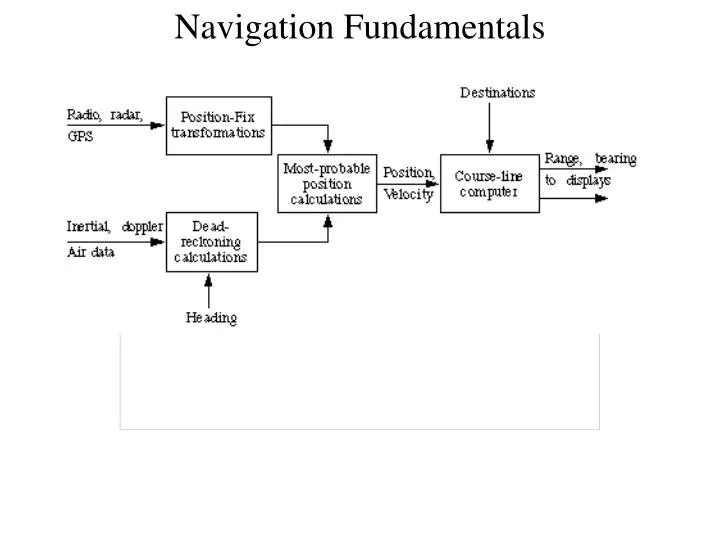
Navigation Fundamentals. Navigation Fundamentals Geometry of the Earth. The Geoid Mean Sea Level (MSL) – Reference surface for altitude Gravitational Equipotential surface. Navigation Fundamentals Geometry of the Earth. The Geoid is a very irregular shape.

E N D
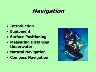
Navigation FundamentalsGeometry of the Earth The Geoid Mean Sea Level (MSL) – Reference surface for altitude Gravitational Equipotential surface
Navigation FundamentalsGeometry of the Earth • The Geoid is a very irregular shape. • Need something mathematically simpler to use for navigation (and surveying). • Use an ellipsoid (an ellipse rotated about the z axis) • defined by: • semi major axis (a) • eccentricity(e) or flattening(f) • coordinates of centre (x,y,z)
Navigation FundamentalsGeometry of the Earth Surveyers wanted ellipsoids which closely matched the geoid in their part of the world so they generated “best fitting” ellipsoids which minimized the “root square” differences in altitude between the ellipsoids and the geoid
Navigation FundamentalsGeometry of the Earth There are hundreds of Geodetic Systems around the world These are a few:
Navigation FundamentalsGeometry of the Earth With the arrival of GPS, a world-wide ellipsoid was developed. This was called WGS84 (World Geodetic System 1984) Its main characteristics are: a=6378137m f=1/298.257 e2 = 2f-f2 gravity g = 9.78049(1+0.00529 sin2Φ) m/s2
Navigation FundamentalsGeometry of the Earth The difference between the WGS84 Ellipsoid and the geoid is shown below
Navigation FundamentalsGeometry of the Earth • Latitude: • Geocentric/Geodetic
Navigation FundamentalsGeometry of the Earth • Radii of Curvature: • Required to convert linear to angular measurements (displacement and speed) • Prime radius is the radius of a circle which best fits the vertical east-west section through the point in question
Navigation FundamentalsGeometry of the Earth • Meridian Radius of Curvature: • is the radius of a circle which best fits the vertical north-south (meridian) section through the point in question
Navigation FundamentalsGeometry of the Earth • These two give us conversions in two orthogonal directions and are adequate for most applications • Sometimes a more general relation ship is required: • Gaussian Radius of Curvature: • is the radius of a sphere which best fits the ellipsoid at the point in question
Navigation FundamentalsRates of Change The rates of change of latitude and longitude are therefore:
Navigation FundamentalsCoordinate Systems • Several coordinate systems have been devised to meet particular requirements of navigation: The most important of these are: • Earth-Centred, Earth-Fixed (ECEF) - Cartesian • We saw this in the GPS section: • z axis: Earth’ rotation axis • x axis: joins Earth centre and Greenwich meridian • origin: Earth centre of mass
Navigation FundamentalsCoordinate Systems • Geodetic Spherical: • z1 = longitude (degrees) • z2 = latitude (degrees) • z3 = height above reference ellipsoid • Used for most long range navigation except that height is normally height above geoid (MSL)
Navigation FundamentalsCoordinate Systems • Generalized Spherical : • z = local vertical at origin note: origin could be in motion • x, y tangent to earth’s surface at origin, • orientation of x axis depends on situation. e.g. orientation of INS platform
Navigation FundamentalsCoordinate Systems • Locally Level: (specialized case of Generalized Spherical) • z = local vertical at origin (origin is fixed) • x, y tangent to earth’s surface at origin, • orientation of x axis depends on requirements • e.g. centre line of a runway • Useful over a limited area (to where the error in elevation becomes critical)
Navigation FundamentalsCoordinate Transformations The basic rotational coordinate transform was given in the section on GPS. To convert from ECEF to Locally Level (or Generalized Spherical) requires a minimum of 3 rotations
Navigation FundamentalsCoordinate Transformations TOP VIEW y y’ X x’ 90-λ x
Navigation FundamentalsCoordinate Transformations z SIDE VIEW y’’ z’ 90-Φ x’ y’
Navigation FundamentalsCoordinate Transformations y’ N y x’ α E x
Navigation FundamentalsCoordinate Transformations The computations required for this transformation are: E
Navigation FundamentalsCoordinate Transformations Multiplied out this is: Note: Given the values in this matrix, one can find Φ = asin(C33) λ = atan(C32/ C31) α = atan(C13/ C23)
Navigation FundamentalsCoordinate Transformations Example: Φ = asin(C33) = asin(0.707) = 45º λ = atan(C32/ C31) = atan (0.683/0.184) =atan(3.71) = 74.9º α = atan(C13/ C23) = atan(0/0.707) = atan (0) = 0º
Navigation FundamentalsCoordinate Transformations It is sometimes required to transform from ECEF to Spherical Geodetic Coordinates and vice versa
Navigation FundamentalsCoordinate Transformations It is sometimes required to transform from ECEF to Spherical Geodetic Coordinates and vice versa
Navigation FundamentalsDead Reckoning • Dead Reckoning (or DR) is a procedure for determining position based on the knowledge of • True Heading (best available true heading - BATH) • Mag heading + Variation or Inertial • True Airspeed (TAS) • Wind Velocity • It is a predictive technique used in conjunction with Position Fixing
Navigation FundamentalsDead Reckoning Definitions: Note: Wind Direction is the direction the wind is coming FROM
Navigation FundamentalsDead Reckoning Example: Heading: 135 (T) TAS: 480kts Wind Velocity: 50kts at 270(T) Position: 50ºN 50ºW Altitude:36000 Ft. What will be the position of the aircraft in 20 minutes?
Navigation FundamentalsDead Reckoning VE=390 Example: 340 480 VN -340 50
Navigation FundamentalsDead Reckoning Example: ρM=3440.959NM h=5.925NM ρP=3451.168NM cos(50)=0.643 dλ/dt = VE/(ρP+h)cos(Φ) = 390/(3451.168+5.925)·0.643 = 0.176 rad/hour or 10º/hour dΦ/dt = VN/(ρM+h) = -340/(3440.959+5.925) = -0.099 rad/hour or -5.6º/hour
Navigation FundamentalsBest Estimate of Position Modern aircraft usually have several position sensors. It is desirable to use all of the information available to get an estimate of position. We would like to have a method for combining this information in the best possible way. Usually, the information from different sources has different accuracies and we would like to make sure that the most accurate source has the greatest influence on the final result
Navigation FundamentalsBest Estimate of Position This is done by weighting the input values with factors derived from their variances (E((x-m)2) or σ2 Assume we have 3 sources of x position, x1, x2 and x3 whose variances are σ12, σ22 and σ32 respectively. We want to find x First we form D = σ12 σ32 + σ22 σ32 + σ22 σ32
Navigation FundamentalsBest Estimate of Position The three weighting factors w1,w2, and w3 are formed as follows w1= (σ22· σ32)/D w2= (σ12· σ32)/D w3= (σ12· σ22)/D and finally x = w1x1 + w2x2 + w3x3
Navigation FundamentalsBest Estimate of Position Deterministically Biased Sensors (e.g. INS) In systems like INS, some of the errors are a function of initial conditions and can be considered deterministic during the flight. e.g. the INS error due to gyro bias:
Navigation FundamentalsBest Estimate of Position This has a known shape: and thus by measuring a few points, its future values can be forecast
Navigation FundamentalsBest Estimate of Position Kalman Filters
Navigation FundamentalsBearing and Distance Calculation The position calculation give latitude and longitude but the pilot usually wants to know the direction and distance to the the next waypoint. The method used depends on the distances involved. Short Distances: Assume Flat Earth Model x=x0 + VEdt y=y0 + VNdt where x0 and y0 are the coordinates of the Starting Point
The True bearing and distance to the next waypoint are then: BT = tan-1 (x-x1)/(y-y1) D = (x-x1)2 +(y- y1)2 where x1 andy1 are the coordinates of the waypoint The pilot usually wants relative bearing to the waypoint This is BT - ψ where ψ is the heading of the aircraft Navigation FundamentalsBearing and Distance Calculation
Navigation FundamentalsBearing and Distance Calculation x0,y0 ψ BT x,y BR x1,y1
Navigation FundamentalsBearing and Distance Calculation For longer distances or where better accuracy is required, spherical trigonometry is used. Spherical Trigonometry deals with triangles on the surface of a sphere. The sides of all triangles are segments of Great Circles A Great Circle is the intersection of a sphere with a plane passing through it’s the sphere’s centre
Navigation FundamentalsBearing and Distance Calculation All sides and angles in spherical trigonometry are give in terms of angles. This is because the relationships are true for spheres of any size. For a particular sphere, the relationship between the linear length of the side of a triangle and the angular length is the radius of the sphere. s = R·θ
Navigation FundamentalsBearing and Distance Calculation To calculate bearing and distance we have to generate a triangle. Two sides are always drawn from the Pole to the two end points in question. Their lengths are 90º minus the latitude of the given point The included angle is always the difference between the longitudes of the two points The two sides are always meridians and thus run true North and South
Navigation FundamentalsBearing and Distance Calculation Δλ 90-Φ2 90-Φ1 B2 P2 B1 L P1 Note: Bearing from P1 to P2 is B1 Bearing from P2 to P1 is 360º - B2
Navigation FundamentalsBearing and Distance Calculation The distance is converted to linear measure by multiplying the angle of the side by the Gaussian radius of curvature