Download
1 / 83
880 likes | 1.27k Views
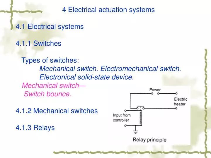
4 Electrical actuation systems 4.1 Electrical systems 4.1.1 Switches Types of switches: Mechanical switch, Electromechanical switch, Electronical solid-state device . Mechanical switch— Switch bounce . 4.1.2 Mechanical switches 4.1.3 Relays.

E N D
4 Electrical actuation systems 4.1 Electrical systems 4.1.1 Switches Types of switches: Mechanical switch, Electromechanical switch, Electronical solid-state device. Mechanical switch— Switch bounce. 4.1.2 Mechanical switches 4.1.3 Relays
4.1.4 Solid-state switches Diode Thyristors, Triacs, Transisters.
4.1.5 Solenoids solenoid can be used to provide electrically operated actuators.
NPNIGBT PNPIGBT (+) Collector (-) Collector (+) Base (-) Base (-) Emitter (+) Emitter NPNIGBT PNPIGBT (+) Collector (-) Collector (+) Base (-) Base (-) Emitter (+) Emitter IGBT – Insulated or Isolated Gate Bipolar Transistor IGBT combines the positive attributes of BJTs and MOSFETs. BJTs have lower conduction losses in the on-state, especially in devices with larger blocking voltages, but have longer switching times, especially at turn-off while. MOSFETs can be turned on and off much faster, but their on-state conduction losses are larger, especially in devices rated for higher blocking voltages. IGBTs have lower on-state voltage drop with high blocking voltage capabilities in addition to fast switching speeds.
4.2 Stepping motors Producing rotation through equal angles, the so-called steps, for each digital pulse supplied to its input.
Solid-state electronics is used to switch the d.c. supply between the pairs of stator windings.
Terminology: Holding torque Pull-in torque pull-out torque Pull-in rate pull-out rate Slew range.
4.3 Motors Electromagnetic force (EMF) 1. Where L is the length of conductor in a magnetic field, I is the current of the conductor, and B is flux density of the magnetic field. 2. is the back e.m.f, is the magnetic flux.
Electric Motors • Basic types • DC Motors: speed and rotational direction control via voltage • Easy to control torque via current • low voltage • linear torque-speed relations • Quick response • AC Motors: smaller, reliable, and cheaper • speed fixed by AC frequency • low torque at low speed • difficult to start
DC Motors: Principles of Operation A wire carrying current experiences a force in a magnetic field. Induced force Current (amp) Length of wire in the direction of i (m) q Magnetic Flux Density (Tesla)
Electromagnetic Force A wire carrying current in a magnetic field. F = ilB i (l = wire length)
Electromagnetic Force • The force is perpendicular to both the magnetic field and current
A voltage is induced in a wire moved in a magnetic field generators Induced voltage (volt) Velocity of wire (m/s) v Electromagnetic Force eindis also called electromotive force (EMF感应电动势) + + + eind eind =vBl l (l = the wire length) - - -
Principle of Electric Motors • Fundamental principle behind electric motors • Current running through coil in magnetic field experiences forces that cause it to rotate
Fundamental characteristics of DC Motors End view Time 0 End view Time 0+ Shifting magnetic field in rotor causes rotor to be forced to turn
Nature of commutation Power is applied to armature windings From V+ Through the +brush Through the commutator contacts Through the armature (rotor) winding Through the – brush To V- Rotation of the armature moves the commutator, switching the armature winding connections Stator may be permanent or electromagnet
Armature Armature conductors Field coil Field pole Commutator Brush Brush wear Brushless Excitation of motors:
(a) Series: highest starting torque and greatest no-load speed. (b) shunt: lowest starting torque, a much lower no-load speed and has good speed regulation. (c) compound: high starting torque and good speed regulation. (d) separate:a special case of the shunt wound motor and ease to revert the direction. The speed of such d.c motors can be changed by either changing the armature current or the field current. The variable voltage is often obtained by an electronic circuit.
Permanent Magnet DC Motors Have permanent magnets rather than field windings but with conventional armatures. Power only to armature. Short response time Linear Torque/Speed characteristics similar to shunt wound motors. Field magnetic flux is constant Current varies linearly with torque. Self-braking upon disconnection of electrical power Need to short + to – supply, May need resistance to dissipate heat. Magnets lose strength over time and are sensitive to heating. Lower than rated torque. Not suitable for continuous duty May have windings built into field magnets to re-magnetize. Best applications for high torque at low speed intermittent duty. Servos, power seats, windows, and windshield wipers.
4.4 A.C. motors Single phase (low power) and Poly phase (high power) Induction (Cheaper) and Synchronous motors Single-phase squirrel-cage induction motor: not self-starting, the rotor rotates at a speed determined by the frequency of the alternating current applied to the stator (synchronous speed), there is difference between the rotor speed and synchronous speed (slip).
Three-phase induction motor: there is rotating magnetic field which completes one rotation in one full cycle of the current, self-starting, the direction of rotation is reversed by interchanging any two of the line connections. Synchronous motors: its rotor is a permanent magnet, not self-starting, used in the case when the precise speed is required.
Inducing magnetism in the rotor Difference between angular velocity of rotor and angular velocity of the field magnetism causes squirrel cage bars to cut the field magnetic field inducing current into squirrel cage bars. This current in turn magnetizes the rotor
A.C. motor is cheaper, more rugged, reliable and maintenance free. • Speed control of A.C. motor is more complex than with d.c. motors.
4.4.1 Brushless permanent magnet d.c. motors High performance, reliability and low maintenance. Current-carrying conductors are fixed and the magnet moves. The current to the stator coils is electronically switched, the switching being controlled by the position of the rotor so that there are always forces acting on the magnet causing it to rotate in same direction.
4.4.2 Speed and position control of D.C motors PWM modulation:
4.4.3 A.C servo system D.C./A.C. Inverter
PWM Variable Frequency Drives AC to DC converter and a DC to AC converter (inverter) Inverter frequency and voltage output can be varied to allow motor speed to be varied. Very efficient and cost effective variable speed