THE BEAGLE 2 LANDER
Beagle2, All Rights Reserved. Courtesy of ESA. THE BEAGLE 2 LANDER. The British led effort to land on Mars, as part of the European Space Agency's Mars Express Mission, to be launched in June 2003. . Beagle2, All Rights Reserved. Courtesy of ESA. The Mars Express.


THE BEAGLE 2 LANDER
E N D
Presentation Transcript
Beagle2, All Rights Reserved Courtesy of ESA THE BEAGLE 2 LANDER The British led effort to land on Mars, as part of the European Space Agency's Mars Express Mission, to be launched in June 2003. Beagle2, All Rights Reserved Courtesy of ESA
The Mars Express • European Space Agency Mission to Mars, to arrive on the 26th of December 2003. • THE MARS EXPRESS ORBITER: • Designed to obtain high-resolution photo geology and mineralogical mapping of the Mars surface and mapping of the atmospheric composition. • THE BEAGLE2 LANDER • Designed to characterise the landing site geology, mineralogy, and geochemistry, the physical properties of the atmosphere and surface layers, collect data on martian meteorology and climatology, and search for possible signatures of life.
ESA The European Space agency exists to provide for and to promote, for exclusively peaceful purposes, cooperation among European States in space research and technology and their space applications. Thus, ESA missions draw and the resources and expertise of all participating European countries to enable a space program that a single country could not sustain on its own. BNSC is Britain’s space agency - The UK is the world's second biggest user of space data and technology. BNSC supports programmes of uniquely valuable space science, assists UK competitiveness in world markets, opens up operational systems for the future bring commercial returns, and helps us understand our changing Earth.
Partners in Beagle2 • Science and Technical Lead – the Open University in Partnership with the University of Leicester. Mission Management Expertise also from Leicester. • Prime Engineering Contractor – ASTRIUM • Entry, descent and landing system (EDLS) – The Martin-Baker Aircraft Company BACKED BY: • BNSC – Britain’s space agency (Major funding from the Department of Trade and Industry and the Particle Physics and Astronomy Research Council ) • The European Space Agency • Funding from the Welcome Trust, a charity biomedical research organisation, which provided funding for the miniature mass spectrometer
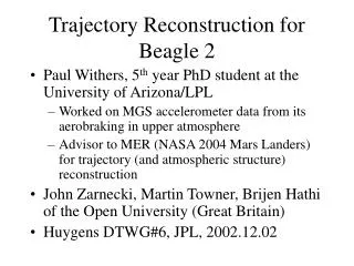
Timeline 1975 • 1975 The NASA Viking Missions. The Viking landers analyse martian rock for signs of life, scientists discount the possibility of life on Mars. Mars landing missions are de-prioritised. • 1975 – Present. Research into martian meteors receives a boost now that scientists can identify martian rock. • Orbiting pictures of Mars indicate that water once flowed on Mars’s surface. • August 1996 – NASA scientists discover traces of fossil bacteria in a martian meteor - huge Public interest. • April 2001 – NASA launches Odyssey, a Mars Orbiter. • June 2003 – The ESA mission ‘Mars Express’ will be launched and will consist of a Mars Orbiter and a Mars Lander, Beagle2. • June 2003 - NASA will launch 2 Mars Rovers, to explore the surface at a rate of 100m per day. Viking Missions 1985 NASA Fossil 1995 2005 Mars Express
Mars Facts • Mars is about one tenth the mass of the earth and one and a half times the earth distance away from the sun. • One Martian Day is 24 hours, 37 minutes and 22 seconds. • One Martian Year is 687 Earth days. • Highest point - Olympus Mons - the largest mountain in the Solar System rising 24 km above the surrounding plain. Its base is more than 500 km in diameter and is bordered by a cliff 6 km high. • The Mars surface features the Hellas Basin in the southern hemisphere, which is a massive impact crater 2,300km in diameter and more than 9km from top to bottom. • Gravity Constant, 3.72m/s2 • Average Temperature, -55 degrees • Minimum Temperature, -130 degrees • Maximum Temperature 27 degrees.
Mars Science • Mars is thought to have formed in a similar way to the earth, form hot gases. Both have hard crusts and dense cores and are made from the same materials, though in different proportions. The composition of Mars core and what goes on beneath the surface is entirely unknown. • Mars is smaller, has lower gravity and is colder than the earth. The thin atmosphere consists almost entirely of carbon dioxide with only very small fractions of nitrogen, argon, oxygen, and a few other rare gases. • Mars may still be volcanically active. There's evidence of lava flows from the major volcanoes as little as a few million years ago. • Mars shows evidence of free-flowing water, possibly as recent as 600,000 years ago.
The Search For Life • A meteor which fell in Egypt in 1911 had the first evidence that martian carbonates (a mineral deposited in water) existed. • The 1996 meteor in which fossilised bacteria were found showed the deposition of carbonate at between 10 and 90 degrees, just right for life. • All living things leave evidence of existence, however doubt remains as to whether the fossil bacteria are actually from Mars. There is no way to prove that the bacteria are definitely from Mars, however the theories on how else they could have got there are equally implausible. • We now know that micro-organisms on Earth are far more tenacious and adaptable than it was realised at the time of Viking. • Exobiologists believe that the most likely location of evidence of life on Mars is in the soil underneath boulders, where the organic matter has not been degraded by the harsh oxidising effects of the Mars atmosphere. The NASA fossil Mars Meteorite
SCIENTIFIC OBJECTIVES Search for evidence of the presence of Water. Analyse soil samples for the presence of organic material. Measure the atmospheric composition. Analyse the composition of rock and perform age dating. Measure environmental conditions and document the seasonal variations over the course of a martian year. OTHER OBJECTIVES Raise the profile of Science Technology and Engineering and foster public support for future missions to Mars. Provide a hotbed of technology that can be used to good effect in the future. E.g. The miniature mass spectrometer for medical applications, where instruments must be small, portable, robust and sterile. The Beagle2 Mission
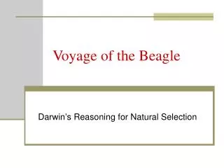
Beagle2 Interesting Facts • Beagle2 is named after HMS Beagle, which was the ship on which Charles Darwin embarked on an expedition which lead to his famous work ‘On the origin of species’. • With a landed mass of less than 30kg, Beagle 2 represents the most ambitious science payload to systems mass ratio ever attempted (almost 1/3 of payload). • A Damien Hirst poster of an array of dots is to be used to calibrate the sensory instruments of the Beagle2 lander before takeoff and after landing. The colour and the mineral content of the paint will analysed before takeoff and after landing. • Upon successful landing, a recording from the British Band ‘Blur’ will be broadcast back to earth. • Approximate Beagle2 cost £40 Million (source, NASA web-site). Beagle2, All Rights Reserved Damien Hirst Spot Painting
Getting to Mars • Launch mass of 1165 kg. • To be launched by the Soyuz / Fregat rocket, which has been in service since 1963 and has a 98% success rate. • Mars Express arrives on 26th December 2003. • Beagle2 is released 5 days prior to this and coasts for 5 days into the martian atmosphere. • After initial deceleration from simple friction, parachutes will be deployed and about 1 km above the surface large gas bags will inflate to protect the lander when it hits the surface. • Parachutes were designed by Lindstrand Balloons, are high performance and light weight and feature a way of packing that enables deployment at very high speeds.
The Landing Site • The landing site was chosen as one place where geological surveys indicate the relatively recent presence of water. • The site is a a large, flat sedimentary basin straddling the relatively young northern plains and ancient southern highlands, where traces of life could have been preserved. • The temperature range between night and day was a crucial factor in choosing the site. Experiments will be carried out at night to generate heat and help keep beagle2 warm • Since Beagle2 is to land by the use of gas filled airbags, slope and frequency of boulders were considered. The surface should be fairly smooth, but with some boulders present so that analysis can be carried out. • The exact position, upon landing will be unknown, however scientists will be able to determine the exact position from the reduction in light levels as Mars’s moons, Phobos and Deimos pass overhead. The landing Site, Courtesy of ESA
The Landing Sequence 1) Beagle2 probe batteries charged by the host spacecraft parent vehicle just prior to release 2) Separation of the lander and orbiter – crucial • Braking due to dissipation of heat by the heat shield. 4) Firing of a pilot chute followed by the main chute. 5) Heat Shield Jettisoned 6) Inflation of gas bags for landing 7) landing causes instant disconnection of the chute so that the lander bounces away from the canopy. The ELDS Sequence, Source: Logica ELDS Report
Structure of the Lander • Outer shell for energy absorption and insulation. During the landing process, the lander must withstand a static drop of one metre to the ground as the airbags used to cushion the impact are released. The Shell Design by McLaren Composites, incorporating the same technology used to protect F1 Drivers in crashes into spacecraft. • Inner shell of carbon fibre skins on a honeycomb core • Fully sterilised so as not to deposit any spores or microbiology on the planet • Lander is actually two halves and opens in a clam like structure Beagle2, All Rights Reserved Separation of the Orbiter and Lander Beagle2, All Rights Reserved Structure of the Beagle2 Lander
Beagle2 Equipment THE ROBOTIC ARM Developed by the University of Leicester. The arm was originally developed to assist with the deployment of instruments, however considerable weight was saved by integrating the instruments into the end of the arm, after which it became known as the PAW Also built into the arm is a grinder and corer, a grinder to get rid of unwanted dust layers and a corer to drill into rock and extract a sample up to 1cm long. THE MOLE DLR Cologne with Transmash (Russia) and Techniospazio (Italy), the mole will provide an element of mobility to the stationary lander The Mole crawls at a rate of 1cm every 6 seconds, burrows millimetres at a time and has a 3m range. The mole collects samples in a cavity at its tip and is recovered with a winch. All Rights Reserved, Beagle2 The Mole Being Tested
Beagle2 Equipment POWER Lander power is provided from a 42-cell battery package, based on lithium ion technology, charged by a 5 panel solar array that are combined to produce a single main supply. The total solar array is about one square metre. TELECOMMUNICATIONS Signals can only be sent to earth via the Mars Express Orbiter and can only be transmitted a few minutes at a time
Beagle2 Instruments THE MASS SPECTROMETER • Mass spectrometer – analyses samples for chemical signatures that indicate life. Highly sophisticated cooking kit. • The facility for heating a solid sample (soil or rock) in steps of increasing temperature, each increment being supplied with freshly generated oxygen - ANY carbon compound present will burn to give carbon dioxide. CAMERAS • A stereo pair of cameras mounted on the robotic arm will provide a panoramic view of the scene around the landing site and monitor the activities during sampling. • One of the cameras has a pop up mirror for a wide angle view, a third camera is a microscope for close examination of rock samples. • Cameras by Mullard Space Science Laboratory, University College London.
Beagle2 Instruments MOSSBAUER SPECTROMETER • Additional Spectrometer to determine the oxidisation state of iron. The high rate of oxidisation is what gives Mars its characteristic colour. • Provided by the University of Mainz in Germany. X-RAY ANALYSIS • The X-ray detector which is carried on Beagle 2 will provide elemental compositions from the energy spectrum. The potassium content will be measured for age dating purposes and samples analysed for major elements to classify rock types. • Provided by the University of Leicester ENVIRONMENTAL SENSORS • Environmental sensors are present to analyse the atmosphere for meteorological conditions such as wind and pressure and also UV flux, radiation and the presence of oxidising species in the atmosphere.
Data Management • The common electronics provides the lander with power management and conditioning, power converters, the central processor, descent electronics, pyrotechnic supplies, motor drives, data handling and experiment interfaces. • A 32-Bit processor is the hub of beagle2. • Whenever possible the electronic systems have been gathered together so that common functions are not duplicated and connections are short. • For thermal reasons, the electronics boards and battery are situated in combination. • A robust and failure-tolerant design • Software for EDLS by LOGICA
The Airbags • The idea of airbags to cushion the landing was first used in the NASA Pathfinder mission in 1996. The Pathfinder lander impacted the surface at a speed of 18m/s and bounced 12 metres into the air, before rolling and coming to rest. • Beagle2 Is predicted to hit the surface with a force equivalent to 200 times that due to gravity. • The use of airbags as a means of landing helps to keep the weight as low as possible. • WS Atkins were commissioned to carry out a finite element analysis of the airbag bounce dynamics, using the LS-DYNA code, to establish confidence in the landing behaviour predicted by the airbag manufacturer. Beagle2, All Rights Reserved
A Successful Landing “The design case is equivalent to pushing your PC off a chair (on Earth) onto a concrete floor and expecting it still to work .”,the Beagle2 web-site. Criteria for a successful landing are: • The lander itself must not strike the ground. • The lander must not be subject to decelerations or reaction loads that will cause damage. • The strain limit of the airbag material must not be exceeded. • The lander must be capable of being deployed, regardless of its orientation. Beagle2, All Rights Reserved Some of the inside of Beagle2
Segment Spherical Outer Wall The Lander-Airbag System comprise three separate airbags, each of which forms a 120 degree segment of a sphere Baffle Spoke Cone Fan Patch and Fan Patch Spoke Spoke Lander Pocket Segment Walls The Finite Element Model • The model follows the actual geometry very closely. The inflation sequence is not modelled. • The 3 Air Bags are connected by stitching on the outside of the overall sphere, which are modelled as spring elements. • Internally each bag contains “spokes”, which provide stiffness and structure to the bag. • The outside of the bag is covered by an abrasive layer to prevent sliding on the impact surface.
The Sequence of A Bounce • Stage 1 – The bag impacts the surface, kinetic energy normal to the surface reduces. • Stage 2 – Work is done on the gas as the bag is compressed and there is a small increase in strain energy within the airbag fabric. There will also be energy dissipation due to sliding friction, heat loss to the atmosphere and damping. • Stage 3 – Kinetic energy increases once more as the bag bounces away from the surface.
Landing On Rocks • At the request of Martin Baker, the model was reworked to include rocks, modelled as rigid walls, that could be easily changed in size, to model obstacles in the path of the lander. • These are the sort of conditions expected at the landing site.
Airbag Separation • It was found that lander orientation, when it comes to rest, has a significant effect on the success of the release sequence. • Variations in the static drop experienced by the lander were between 45mm and 3.5m, depending on the orientation. • Recommendations were made concerning possible ways to reduce this risk, such as positioning the lander off-centre within the airbags. Beagle2, All Rights Reserved
Model Accuracy • The model shows reasonable bounce dynamics and credible results. • The model is sensitive to the value of the damping co-efficient used in the analysis and the shear modulus of the fabric material. • LS-DYNA does not take account of energy lost due to heat dissipation during impact and heat loss to the atmosphere. • Analysis of the air-bag separation phase of the landing resulted in recommendations concerning the design, that may have otherwise been overlooked. • Good agreement was found between hand calculations for hoop stress in the material and those derived from the FE model.
Modelling Challenges • LS-DYNA must be set up so that the airbag behaviour can be modelled accurately, without instabilities in the model and with a manageable analysis run-time. • A judgement must also be made over which results constitute real behaviour and which are due to numerical instabilities in the model. • A sensitivity study was conducted, which found that element behaviour in areas of high crumpling was stable when using time-steps of 0.5μs and element edge lengths of 15mm. Stability was also dependent on using LS-DYNA version 960, which exhibits more reliable behaviour in areas of contact. • LS-DYNA was set up to run the analysis at the limit of its capability, to give the most realistic results possible.
Modelling Applications Containment Test Simulation Beagle 2 Lander OPS
Modelling Applications Aerospace Structures Fluid-Structure Interaction Rail Structures Thermal
Modelling Applications Occupant and Interior Modelling Ship Impact Assessment Automotive Crashworthiness
Civil Applications Case Study - Structural assessment of the A36 Skew Masonry Bridge Atkins was commissioned by the Highways Agency to carry out the structural assessment of the A36 Skew Masonry Bridge located in Salisbury (Wiltshire). The traditional MEXE method could not be used to assess the bridge in question due to its high angle of skew (50). The ABAQUS model predicts the formation of hinges in line with standard arch theory. In addition, the model demonstrates that although a limited amount of cracking may occur, the bridge should withstand the ultimate factored loading due to three 44 tonne vehicles. The Atkins A36 Skew Masonry Bridge FE Model Comparison Between Predicted Crack Locations and Effective Arch Ring Theory
Civil Applications Case Study – Seismic Qualification of Dungeness B Power Station Atkins is experienced in the seismic assessment and qualification of nuclear power stations, with British Energy and Magnox both being major clients. Dungeness B Power Station The model was used in the seismic qualification work undertaken by Bristol for the structure and critical plant. The structure is modelled using beam and shell elements. Seismic Acceleration Time Histories are input into the ground nodes in order to model the motion of the earthquake. Isometric view of Dungeness B ABAQUS Finite Element Model.
Civil Applications Case Study – Design of Steelwork Restraint for Lower Gas Duct The pressure circuits at Sizewell A Nuclear Power Station use CO2 gas to transfer the heat from the reactor to the boilers. Each duct is supported from hangers in order to accommodate duct movement during the thermal cycle of the reactor. If a hanger were to fail, the duct would fall resulting in overstress at the reactor nozzle and a potential breach of nuclear safety • Atkins designed, commissioned and installed a steelwork frame restraint system to limit the distance through which the lower gas duct could fall. • Using FEA the restraint was designed to resist the additional dynamic load caused by impact of the duct. In order to prevent breach of the duct the flanges of the restraint beam were reduced in section at the beam ends and centre span in order to control the formation of plastic hinges. This was verified using LS-DYNA. The remainder of the restraint was designed to BS5950.
The Future • 2007 – The Netlander Mars mission, which will include four landing craft to investigate the interior and subsurface of Mars. One aspect will be to search for water. • 2014 – NASA sample and return mission to Mars to bring back Mars rock from the surface. Up to this point, most spacecraft are designed to be disposable. • THE POSSIBILITIES • A network of Geophysical Stations on Mars. • Future manned missions to Mars……….