Download
1 / 20
200 likes | 326 Views
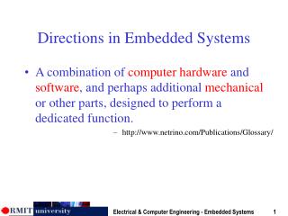
4-Integrating Peripherals in Embedded Systems (cont.). Analog-to-digital converters. Why Analog? Not everything is digital! Even digital signaling has analog aspects (!?) Analog circuits and analysis are still necessary Physical phenomena (i.e., the real world) are usually analog

E N D
Analog-to-digital converters • Why Analog? • Not everything is digital! • Even digital signaling has analog aspects (!?) • Analog circuits and analysis are still necessary • Physical phenomena (i.e., the real world) are usually analog • Many sensors are analog (potentiometer, phototransistor, thermo-sensor, microphone) • Many actuators are analog (solenoid, speakers) • Some signals need to be processed in analog domain before conversion to digital (amplification, filtering, linearization)
Vmax = 7.5V 4 4 1111 7.0V 1110 6.5V 1101 3 3 6.0V 1100 5.5V 1011 2 2 analog input (V) analog output (V) 5.0V 1010 4.5V 1001 1 1 4.0V 1000 3.5V 0111 time time 0110 3.0V t1 t2 t3 t4 t1 t2 t3 t4 2.5V 0101 0100 1000 0110 0101 0100 1000 0110 0101 2.0V 0100 Digital input Digital output 1.5V 0011 1.0V 0010 0.5V 0001 0V 0000 analog to digital digital to analog proportionality Analog-to-digital converters
Analog to Digital Conversion Instantaneous amplitudes of continuous analog signal, measured at equally spaced points in time. A series of “snapshots” Error=1/2 LSB
Analog to Digital Overview Sampling Rate How often analog signal is measured [samples per second, Hz] Example: 44,100 Hz Sampling Resolution [a.k.a. “sample word length,” “bit depth”]Precision of numbers used for measurement: the more bits, the higher the resolution. Example: 16 bit
Sampling Rate Determines the highest frequency that you can represent with a digital signal. Nyquist Theorem: Sampling rate must be at least twice as high as the highest frequency you want to represent. Capturing just the crest and trough of a sine wave will represent the wave exactly.
Digital and Analog Conversion • A/D transfer function: • 10-bit ADC converter • 1024 voltage levels between 0V and VREF • 10-bit digital value • Usually VDD=VREF • (e-Vmin)/(Vmax-Vmin)=d/(2^n-1), • When Vmin=0: • e/Vmax=D/(2^n-1) • In general • Vmax match 2^n-1 • Vmin match 0 • How does D/A and A/D conversion work?
D/A Conversion • D/A is simpler than A/D • Different resisters and an inverted OpAmp, to implement a weighted summer. • Example: 4-bit D/A • If D3D2D1D0=0001 (i.e., 0V,0V,0V,-5V) • Vo=-1.1*(D0/17.6+D1/8.8+D2/4.4+D2/2.2) =0.3125V • If D3D2D1D0=1111 (i.e., -5V,-5V,-5V,-5V) • Vo=-1.1*(D0/17.6+D1/8.8+D2/4.4+D2/2.2) =4.6875V
A/D Conversion • Use D/A converter to generate different analog values and compare • Control logic decides which values to try • When comparison complete, best match is put on output • How can D/A be matched to input in fewest steps?
Successive Approximation (SAR) ADC • Matching strategies: • Counting conversion (slow) • Successive approximation (faster) • Successive Approximation: • Basically binary search: • Exact 10 steps instead of 1024, SAR is fast!
0 0 0 0 0 0 0 0 0 1 0 1 0 0 0 0 0 1 0 0 0 0 0 0 0 1 0 1 0 1 0 0 0 1 0 0 0 0 0 0 0 1 0 1 0 1 0 0 0 1 0 1 0 0 0 0 0 1 0 1 0 1 0 1 Digital-to-analog conversion using successive approximation Given an analog input signal whose voltage should range from 0 to 15 volts, and an 8-bit digital encoding, calculate the correct encoding for 5 volts. Then trace the successive-approximation approach to find the correct encoding. 5/15 = d/(28 - 1)=d/255 d= 85 Encoding: 01010101 Successive-approximation method ½(Vmax + Vmin) = 7.5 volts Vmax = 7.5 volts. ½(5.63 + 4.69) = 5.16 volts Vmax = 5.16 volts. ½(7.5 + 0) = 3.75 volts Vmin = 3.75 volts. ½(5.16 + 4.69) = 4.93 volts Vmin = 4.93 volts. ½(7.5 + 3.75) = 5.63 volts Vmax = 5.63 volts ½(5.16 + 4.93) = 5.05 volts Vmax = 5.05 volts. ½(5.63 + 3.75) = 4.69 volts Vmin = 4.69 volts. ½(5.05 + 4.93) = 4.99 volts
Analog to Digital Recording Chain ADC Microphone converts acoustic to electrical energy. It’s a transducer. Continuously varying electrical energy is an analog of the sound pressure wave. ADC (Analog to Digital Converter) converts analog to digital electrical signal. Digital signal transmits binary numbers. DAC (Digital to Analog Converter) converts digital signal in computer to analog for your headphones.
Analog Representations of Sound Magnified phonograph grooves, viewed from above: When viewed from the side, channel 1 goes up and down, and channel 2 goes side to side.
Common Sampling Rates Which rates can represent the range of frequencies audible by (fresh) ears? Most software can handle all these rates.
7 6 5 4 3 2 1 0 3-bit Quantization A 3-bit binary (base 2) number has 23 = 8 values. Amplitude Time — measure amp. at each tick of sample clock A rough approximation
The Digital Audio Stream It’s just a series of sample numbers, to be interpreted as instantaneous amplitudes: one for every tick of the sample clock. Previous example: 11 13 15 13 10 9 6 1 4 9 15 11 13 9 This is what appears in a sound file, along with a header that indicates the sampling rate, bit depth and other things.
Audio File Size CD Stereo characteristics: - Sampling rate: 44,100 samples per second (44.1 kHz) - Sample word length: 16 bits (i.e., 2 bytes) per sample - Number of channels: 2 (stereo) How big is a 5-minute CD-quality sound file?
Audio File Size How big is a 5-minute CD-quality sound file? 44,100 samples * 2 bytes per sample * 2 channels = 176,400 bytes per second or =1.41 M bits per second Note for DVD audio: 48,000 samples instead of 44,100 = 1.536 Mbps CD 5 minutes * 60 seconds per minute = 300 seconds 300 seconds * 176,400 bytes per second = 52,920,000 bytes = c. 50.5 megabytes (MB)
MPEG Compression • MPEG 1-Layer 3 (.mp3) • “Motion Picture Experts Group” • Different levels for different purposes • E.g. MPEG 2 used for DVDs • Takes out parts of the sound signal that humans can’t hear • How does the size change? • Lossy compression • #: The 384 is 1/4th of the 1.536 Mbps More on MPEG Compression http://www.cs.wustl.edu/~jain/cis788-99/ftp/compression/index.html