Download
1 / 65
650 likes | 963 Views
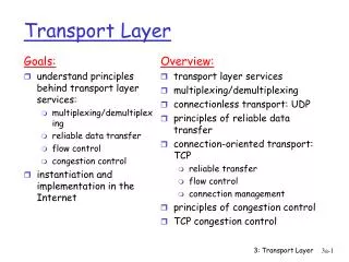
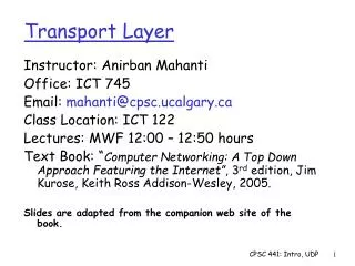
Transport Layer. Part 2. TCP Flow Control, Congestion Control, Connection Management, etc. Encapsulation in TCP/IP. IP datagram. point-to-point: one sender, one receiver reliable, in-order byte stream: no message boundaries pipelined: TCP congestion and flow control set window size

E N D
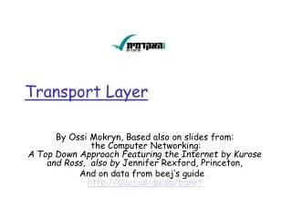
Transport Layer Part 2 TCP Flow Control, Congestion Control, Connection Management, etc.
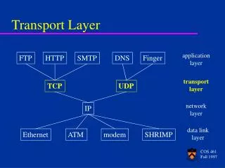
Encapsulation in TCP/IP IP datagram
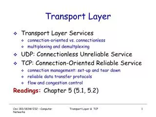
point-to-point: one sender, one receiver reliable, in-order byte stream: no message boundaries pipelined: TCP congestion and flow control set window size send & receive buffers TCP: Overview Error detection, retransmission, cumulative ACKs, timers, header fields for sequence and ACK numbers • full duplex data: • bi-directional app. data flow in same connection • MSS: maximum segment size • connection-oriented: • handshaking (exchange of control msgs) init's sender, receiver state before data exchange • flow controlled: • sender will not ''flood'' receiver with data application application writes data reads data socket socket door door TCP TCP send buffer receive buffer segment
Recall application application writes data reads data socket socket door door TCP TCP send buffer receive buffer Packet -> • Reliable Data Transfer Mechanisms: • Checksum • Timer • Sequence number • ACK • NAK • Window, pipelining - Verification of integrity of packet - Signals necessary re-transmission is required - Keeps track of which packet has been sent and received - Indicates receipt of packet in good or bad form - Allows for the sending of multiple yet-to-be-acknowledged packets
Internet Checksum Example • Note • When adding numbers, a carryout from the most significant bit needs to be added to the result • Example: add two 16-bit integers 1 1 1 1 0 0 1 1 0 0 1 1 0 0 1 1 0 1 1 1 0 1 0 1 0 1 0 1 0 1 0 1 0 1 1 1 0 1 1 1 0 1 1 1 0 1 1 1 0 1 1 1 1 0 1 1 1 0 1 1 1 0 1 1 1 1 0 0 1 0 1 0 0 0 1 0 0 0 1 0 0 0 0 1 1 data wraparound 1 sum checksum 1 1 1 1 1 1 1 1 1 1 1 1 1 1 1 1 To check:
Connection Oriented Transport: TCP • TCP Segment Structure • SEQ and ACK numbers • Calculating the Timeout Interval • The Simplified TCP Sender • ACK Generation Recommendation (RFC 1122, RFC 2581) • Interesting Transmission Scenarios • Flow Control • TCP Connection Management
32 bits URG: urgent data (generally not used) counting by bytes of data (not segments!) source port # dest. port # ACK: ACK # valid head len not used rcvr window size U A P R S F PSH: push data now (generally not used) # bytes the rcvr is willing to accept checksum URGent data ptr RST, SYN, FIN: connection established (setup, tear down commands) Options (variable length) application data (variable length) Internet checksum (as in UDP) TCP segment structure Header sequence number acknowledgement number We can view these teeny-weeny details using Ethereal. In practice, PSH, URG, and the Urgent Data Pointer are not used.
Example Suppose that a process in Host A wants to send a stream of data to a process in Host B over a TCP connection. • Assume: • Data stream: file consisting of 500,000 bytes • MSS: 1,000 bytes • First byte of data stream: numbered as 0 TCP constructs 500 segments out of the data stream. 500,000 bytes/1,000 bytes = 500 segments
TCP sequence #'s and ACKs ... Sequence. Numbers (#'s): • byte stream 'number' of first byte in segment's data • Do not necessarily start from 0, use random initial number R • Segment 1: 0 + R • Segment 2: 1000 + R etc... ACKs (acknowledgment): • Seq # of next byte expected from other side (last byte +1) • Cumulative ACK • If received segment 1, waits for segment 2 • E.g. Ack=1000 + R (received up to 999th byte) Segment 2 Segment 1 0 1 2 3 4 .....999 10001001 1002....1999
Host B Host A User types 'C' Seq=42, ACK=79, data = ‘C’ host ACKs receipt of 'C', echoes back 'C' Seq=79, ACK=43, data = ‘C’ host ACKs receipt of echoed 'C' Seq=43, ACK=80 time simple telnet scenario (with echo on) TCP sequence #'s and ACKs client server Q: how receiver handles out-of-order segments • A: TCP specs. does not say, - decide when implementing I’m sending data starting at seq. num=42 Assuming that the starting sequence numbers for Host A and Host B are: 42 and 79 respectively Send me the bytes from 43 onward ACK is being piggy-backed on server-to-client data
Host B Host A User types 'Hello' Seq=42, ACK=79, data = ‘Hello’ host ACKs receipt of 'Hello', echoes back 'Hello' Seq=79, ACK=47, data = ‘Hello’ host ACKs receipt of echoed 'Hello' send something else Seq=47, ACK=84, data = ‘200’ time Yet another server echo example Host A: seq=42 ack=79 seq=47 ack=84 Host B: seq=79 ack=47 seq=84 ack=50 Seq=84, ACK=50, data = ‘200’ ACK tells about up to what byte has been received and what is the next startingbyte the host is expecting to receive
Q:how to estimate RTT? SampleRTT: measured time from segment transmission until ACK receipt ignore retransmissions, cumulatively ACKed segments SampleRTT will vary, we would want estimated RTT to be ''smoother'' use several recent measurements, not just current SampleRTT TCP Round Trip Time and Timeout Main Issue: How long is the sender willing to wait before re-transmitting the packet? Q:how to set TCP timeout value? • longer than RTT * • note: RTT will vary • too short: premature timeout • unnecessary retransmissions • too long: slow reaction to segment loss * RTT = round trip time
EstimatedRTT = (1-x) * EstimatedRTT + x * SampleRTT • Exponential weighted moving average • influence of given sample decreases exponentially fast • typical value of x: 0.125 (RFC 2988) Timeout = EstimatedRTT + (4 * Deviation) TCP Round Trip Time and Timeout Setting the timeout • EstimatedRTT plus ''safety margin'' • large variation in EstimatedRTT -> larger safety margin • recommended value of x: 0.25 Deviation = (1-x) * Deviation + x * |SampleRTT-EstimatedRTT|
Sample Calculations EstimatedRTT = 0.875 * EstimatedRTT + 0.125 * SampleRTT EstimatedRTT after the receipt of the ACK of segment 1: EstimatedRTT = RTT for Segment 1 = 0.02746 second EstimatedRTT after the receipt of the ACK of segment 2: EstimatedRTT = 0.875 * 0.02746 + 0.125 * 0.035557 = 0.0285 EstimatedRTT after the receipt of the ACK of segment 3: EstimatedRTT = 0.875 * 0.0285 + 0.125 * 0.070059 = 0.0337 EstimatedRTT after the receipt of the ACK of segment 4: EstimatedRTT = 0.875 * 0.0337+ 0.125 * 0.11443 = 0.0438 EstimatedRTT after the receipt of the ACK of segment 5: EstimatedRTT = 0.875 * 0.0438 + 0.125 * 0.13989 = 0.0558 EstimatedRTT after the receipt of the ACK of segment 6: EstimatedRTT = 0.875 * 0.0558 + 0.125 * 0.18964 = 0.0725
RTT Samples and RTT estimates Estimated RTT 300 250 200 150 100 Sample RTT RTT (msec.) The variations in the SampleRTT are smoothed out in the computation of the EstimatedRTT. time
event: data received from application above create, send segment event: timer timeout for segment with seq. number y wait for event wait for event retransmit segment event: ACK received, with ACK number y process ACK FSM of TCP for Reliable Data Transfer Simplified TCP sender, assuming: - one way data transfer - no flow, congestion control
SIMPLIFIED TCP SENDER 00sendbase = initial_sequence number 01 nextseqnum = initial_sequence number 02 03 loop (forever) { 04 switch(event) 05 event:data received from application above 06 create TCP segment with sequence number nextseqnum 07 If (timer is currently not running) start timer for segment nextseqnum 08 pass segment to IP 09 nextseqnum = nextseqnum + length(data) 10 event:timer timeout 11 retransmit not-yet-ACKed segment with smallest Seq. # 12 Start timer 13 event:ACK received, with ACK field value of y 15 if (y > sendbase) { /* cumulative ACK of all data up to y */ 16 sendbase = y 17 If (there are currently any not-yet-ACKed segments) start timer 19 } 20 } /* end of loop forever */ • Assumptions: • sender is not constrained by TCP flow or congestion control • that data from above is less than MSS in size • that data transfer is in one direction only Associated with the oldest unACKed segment
TCPwith MODIFICATIONS SENDER 00sendbase = initial_sequence number 01 nextseqnum = initial_sequence number 02 03 loop (forever) { 04 switch(event) 05 event:data received from application above 06 create TCP segment with sequence number nextseqnum 07 start timer for segment nextseqnum 08 pass segment to IP 09 nextseqnum = nextseqnum + length(data) 10 event:timer timeout for segment with sequence number y 11 retransmit segment with sequence number y 12 compute new timeout interval for segment y 13 restart timer for sequence number y 14 event:ACK received, with ACK field value of y 15 if (y > sendbase) {/* cumulative ACK of all data up to y */ 16 cancel all timers for segments with sequence numbers < y 17 sendbase = y 18 } 19 else {/* a duplicate ACK for already ACKed segment */ 20 increment number of duplicate ACKs received for y 21 if (number of duplicate ACKS received for y is 3) { 22 /* perform TCP fast retransmission */ 23 resend segment with sequence number y 24 restart timer for segment y 25 } 26 } /* end of loop forever */ Why wait for the timeout to expire, when consecutive ACKs can be used to indicate a lost segment With Fast Retransmit
TCP Receiver action Delay sending the ACK. Wait up to 500ms for next segment. If next segment does not arrive in this interval, send ACK immediately send a single cumulative ACK send duplicate ACK, indicating seq. # of next expected byte Immediately send an ACK if segment starts at lower end of gap Event in-order segment arrival, no gaps, everything else already ACKed in-order segment arrival, no gaps, one delayed ACK pending (due to action 1) out-of-order segment arrival with higher than expect seq. # - a gap is detected arrival of segment that partially or completely fills gap TCP ACK generation[RFC 1122, RFC 2581] Receiver does not discard out-of-order segments 1 2 3 4
Host A Host B Host A Host B Seq=92, 8 bytes data Seq=92, 8 bytes data Seq=100, 20 bytes data ACK=100 Seq=92 timeout timeout X ACK=100 loss Seq=92, 8 bytes data Seq=92, 8 bytes data ACK=100 time time premature timeout, cumulative ACKs lost ACK scenario TCP: Interesting Scenarios Simplified TCP version ACK=120 Timer is restarted here for Seq=92 ACK=120 Segment with Seq=100 not retransmitted Retransmission due to lost ACK
Host A Host B Seq=92, 8 bytes data Seq=100, 20 bytes data ACK=100 Seq=92 timeout time TCP: Retransmission Scenario X loss ACK=120 Cumulative ACK avoids retransmission of the first segment.
TCP Modifications:Doubling the Timeout Interval Provides a limited form of congestion control Congestion may get worse if sources continue to retransmit packets persistently. Timer expiration is more likely caused by congestion in the network TimeoutInterval = 2 * TimeoutIntervalPrevious After ACK is received, TimeoutInterval is derived from most recent EstimatedRTT and DevRTT TCP acts more politely by increasing the TimeoutInterval, causing the sender to retransmit after longer and longer intervals. Others: check RFC 2018 – selective ACK
flow control RcvBuffer= size of TCP Receive Buffer RcvWindow = amount of spare room in Buffer receiver buffering TCP Flow Control receiver: explicitly informs sender of (dynamically changing) amount of free buffer space • RcvWindowfield in TCP segment sender: keeps the amount of transmitted, unACKed data less than most recently received RcvWindow sender won't overrun receiver's buffer by transmitting too much, too fast
LastByteRead 100 0 60 50 40 LastByteRcvd RcvBuffer FLOW CONTROL: Receiver EXAMPLE: HOST A sends a large file to HOST B RECEIVER: HOST B – uses RcvWindow, LastByteRcvd, LastByteRead Data from IP Application Process HOST B tells HOST Ahow much spare room it has in the connection buffer by placing its current value of RcvWindow in the receive window field of every segment it sends to HOST A. Initially, RcvWindow = RcvBuffer Application reads from the buffer RcvWindow=RcvBuffer-[LastByteRcvd-LastByteRead]
LastByteACKed 100 0 60 50 40 LastByteSent FLOW CONTROL: Sender EXAMPLE: HOST A sends a large file to HOST B SENDER: HOST A – uses RcvWindow of HostB, LastByteSent, LastByteACKed SENDER: HOST A ACKs from Host B Data To ensure that HOST B does not overflow, HOST A maintains throughout the connection’s life that [LastByteSent-LastByteACKed] <= RcvWindow
FLOW CONTROL Some issue to consider: RcvWindow – used by the connection to provide the flow control service What happens when the receive buffer of HOST B is full ? (that is, when RcvWindow=0) TCP requires that HOST Acontinue to send segments with one data byte when HOST B’s receive window is 0. Such segments will be ACKed by HOST B. Eventually, the buffer will have some space and the ACKs will contain RcvWindow > 0 TCP sends a segment only when there is data or ACK to send. Therefore, the sender must maintain the connection ‘alive’.
TCP Connection Management Recall:TCP sender, receiver establish “connection” before exchanging data segments • Initialize TCP variables: • sequence numbers • buffers, flow control info (e.g. RcvWindow) • Client is the connection initiator In Java,Socket clientSocket = new Socket("hostname","port number"); connect; • Server is contacted by client In Java,Socket accept(); if (connect(s, (struct sockaddr *)&sin, sizeof(sin)) != 0) { printf("connect failed\n"); WSACleanup(); exit(1); } ns = accept(s,(struct sockaddr *)(&remoteaddr),&addrlen);
Client Server Connect (SYN=1, seq=client_isn) Accept (SYN=1, seq=server_isn,ack=client_isn+1) ACK (SYN=0, seq=client_isn+1,ack=server_isn+1) time TCP Connection Management Establishing a connection Three way handshake: Step 1:client end system sends TCP SYN control segment to server (executed by TCP itself) • specifies initial seq number (isn) Step 2:server end system receives SYN, replies with SYNACK control segment • ACKs received SYN • allocates buffers • specifies server’s initial seq. number Step 3:clientACKs the connection with ACK=server_isn +1 • allocates buffers • sends SYN=0 Connection established! This is what happens when we create a socket for connection to a server After establishing the connection, the client can receive segments with app-generated data! (SYN=0)
client server close FIN ACK close FIN ACK timed wait closed TCP Connection Management (cont.) How TCP connection is established and torn down Closing a connection: client closes socket: closesocket(s); Java:clientSocket.close(); Step 1:client end system sends TCP FIN control segment to server Step 2:server receives FIN, replies with ACK. Closes connection, sends FIN.
client server closing FIN closing ACK timed wait closed closed TCP Connection Management (cont.) Step 3:client receives FIN, replies with ACK. • Enters ''timed wait'' - will respond with ACK to received FINs Step 4:server, receives ACK. Connection closed. Note:with small modification, can handle simultaneous FINs. ACK FIN
TCP Connection Management (cont) Used in case ACK gets lost. It is implementation-dependent (e.g. 30 seconds, 1 minute, 2 minutes 12 2 10 TCP server lifecycle 8 4 6 11 TCP client lifecycle 1 9 Connection formally closes – all resources (e.g. port numbers) are released 7 3 5
Flow Control vs. Congestion Control Similar actions are taken, but for very different reasons • Flow Control • point-to-point traffic between sender and receiver • speed matching service, matching the rate at which the sender is sending against the rate at which the receiving application is reading • prevents Receiver Buffer from overflowing Congestion – happens when there are too many sources attempting to send data at too high a rate for the routers along the path • Congestion Control • service that makes sure that the routers between End Systems are able to carry the offered traffic • prevents routers from overflowing Same course of action: Throttling of the sender
Principles of Congestion Control Congestion: • Informally: ''too many sources sending too much data too fast for network to handle'' • different from flow control! • Manifestations: • lost packets (buffer overflow at routers) • long delays (queuing in router buffers) • a top-10 problem!
Network-assisted congestion control: routers provide feedback to End Systems in the form of: single bit indicating link congestion (SNA, DECbit, TCP/IP ECN, ATM ABR) explicit transmission rate the sender should send at Approaches towards congestion control Two broad approaches towards congestion control: End-to-end congestion control: • no explicit feedback from network • congestion inferred by end-systems from observed packet loss & delay • approach taken by TCP 1 2
LastByteSent - LastByteACKed Indirectly limits the sender’s send rate TCP Congestion Control How TCP sender limits the rate at which it sends traffic into its connection? New variable! – Congestion Window SENDER: (Amount of unACKed data)SENDER < min(CongWin, RcvWindow) By adjusting CongWin, sender can therefore adjust the rate at which it sends data into its connection Assumptions: • TCP receive buffer is very large – no RcvWindow constraint • Amt. of unACKed data at sender is solely limited by CongWin • Packet loss delay & packet transmission delay are negligible CongWin Sending rate: (approx.) RTT
TCP Congestion Control TCP uses ACKs to trigger (“clock”) its increase in congestion window size – “self-clocking” Arrival of ACKs – indication to the sender that all is well • Slow Rate • Congestion window will be increased at a relatively slow rate • High rate • Congestion window will be increased more quickly
TCP Congestion Control How TCP perceives that there is congestion on the path? “Loss Event” – when there is excessive congestion, router buffers along the path overflows, causing datagrams to be dropped, which in turn, results in a “loss event” at the sender • Timeout • no ACK is received after segment loss • Receipt of three duplicate ACKs • segment loss is followed by three ACKs received at the sender
sender limits transmission: LastByteSent-LastByteAcked cwnd roughly, cwndis dynamic, function of perceived network congestion How does sender perceive congestion? loss event = timeout or 3 duplicate acks TCP sender reduces rate (cwnd) after loss event Three mechanisms: AIMD slow start conservative after timeout events cwnd rate = Bytes/sec RTT TCP Congestion Control: details
TCP congestion avoidance : additive increase, multiplicative decrease • approach:increase transmission rate (window size), probing for usable bandwidth, until loss occurs • additive increase: increase cwndby 1 MSS every RTT until loss is detected • multiplicative decrease: cut cwnd in half after loss saw tooth behavior: probing for bandwidth cwnd: congestion window size time
when connection begins, increase rate exponentially until first loss event: initially cwnd= 1 MSS double cwndevery RTT done by incrementing cwnd by 1 MSS for every ACK received summary: initial rate is slow but ramps up exponentially fast (doubling of the sending rate every RTT) time TCP Slow Start Host A Host B one segment RTT two segments four segments
after 3 dup ACKs: cwndis cut in half window then grows linearly but after timeout event: cwnd is set to 1 MSS window then grows exponentially Up to a threshold, then grows linearly Refinement: inferring loss Philosophy: • 3 dup ACKs indicates network capable of delivering some segments • timeout indicates a “more alarming” congestion scenario
Q: when should the exponential increase switch to linear? A: when cwndgets to 1/2 of its value before timeout. Implementation: variable ssthresh (slow-start threshold) on loss event, ssthreshis set to 1/2 of cwndjust before loss event Refinement
new ACK . cwnd = cwnd+MSS dupACKcount = 0 transmit new segment(s), as allowed new ACK L cwnd = cwnd + MSS (MSS/cwnd) dupACKcount = 0 transmit new segment(s), as allowed cwnd = 1 MSS ssthresh = 64 KB dupACKcount = 0 cwnd > ssthresh L timeout ssthresh = cwnd/2 cwnd = 1 MSS dupACKcount = 0 retransmit missing segment slow start congestion avoidance timeout dupACKcount == 3 dupACKcount == 3 ssthresh = cwnd/2 cwnd = 1 MSS dupACKcount = 0 retransmit missing segment timeout ssthresh= cwnd/2 cwnd = ssthresh + 3 retransmit missing segment duplicate ACK duplicate ACK ssthresh= cwnd/2 cwnd = ssthresh + 3 MSS retransmit missing segment ssthresh = cwnd/2 cwnd = 1 dupACKcount = 0 retransmit missing segment dupACKcount++ dupACKcount++ fast recovery New ACK duplicate ACK cwnd = cwnd + MSS transmit new segment(s), as allowed New ACK! New ACK! New ACK! cwnd = ssthresh dupACKcount = 0 Summary: TCP Congestion Control
Congestion control TCP’s Congestion Control Service Problem: Gridlock sets-in when there is packet loss due to router congestion The sending system’s packet is lost due to congestion, and is alerted when it stops receiving ACKs of packets sent CLIENT SERVER forces the End Systems to decrease the rate at which packets are sent during periods of congestion
TransportLayer Macroscopic Description of TCP throughput (Based on Idealised model for the steady-state dynamics of TCP) • what’s the average throughout of TCP as a function of window size and RTT? • ignore slow start (typically very short phases) • let W be the window size when loss occurs. • when window is W, throughput is W/RTT • just after loss, window drops to W/2, throughput to W/2RTT. • Throughput increases linearly (by MSS/RTT every RTT) • Average Throughput: .75 W/RTT
TCP Futures: TCP over “long, fat pipes” • Example: GRID computing application • 1500-byte segments, 100ms RTT, desired throughput of 10 Gbps • requires window size W = 83,333 in-flight segments • Throughput in terms of loss rate: • ➜ L = 2·10-10 – a very small loss rate! (1 loss event every 5 billion segments) • new versions of TCP is needed for high-speed environments TransportLayer
TCP connection 1 bottleneck router capacity R TCP connection 2 TCP Fairness Fairness goal: if N TCP sessions share same bottleneck link, each should get an average transmission rate of R/N , an equal share of the link’s bandwidth Go to Summary of TCP Congestion Control