Download
1 / 34
490 likes | 1.28k Views
Lecture 7: Cascade and Ratio Control. Objectives. To understand what is cascade control? When to use? and how to tune? To understand three configurations for ratio control and the advantages and disadvantages of each of them. Cascade Control. Motivation for Cascade Control.

E N D
Lecture 7: Cascade and Ratio Control
Objectives • To understand what is cascade control? When to use? and how to tune? • To understand three configurations for ratio control and the advantages and disadvantages of each of them.
Motivation for Cascade Control • Consider the following gas furnace. • The purpose is to control the temperature of the outlet stream.
Motivation for Cascade Control • One possible solution is to control the temperature using the fuel gas flow valve.
Motivation for Cascade Control • Problem: fuel flow may subject to large fluctuation due to the upstream pressure variation, P. P
Motivation for Cascade Control • Let’s think about the process behavior. • The change in disturbance P will cause a change in outlet temperature, T (in the long run because the process is slow). • But the change in P will more quickly cause a change in the flow rate F. • Fortunately, F is measurable. So, if we can maintain it approximately constant, we can reduce the effect of the disturbance. This is the idea of “cascade control”. v (valve) ??? Q TC P (heating oil)
Motivation for Cascade Control Cascade control solution: try to keep flow constant. This will, hopefully, forbid pressure fluctuations from propagating to the outlet temperature, T.
Cascade Control: Block Diagram • Cascade control requires an additional measurement (usually flow rate) and an additional controller Gc2. • However, large improvement in performance is obtained when the secondary (inner) loop is much faster than primary (outer) loop. disadvantage advantage
Cascade Control Analogy to Management Hierarchy • A cascade is a hierarchy, with decisions transmitted from upper to lower levels. • What are the advantages of a hierarchy?
When to use Cascade Control? If you have a process with relatively slow dynamics (like level, temperature, composition, humidity) and a liquid or gas flow, or some other relatively-fast process, has to be manipulated to control the slow process. How to tune Cascade Controllers? A cascade arrangement should be tuned starting with the innermost loop.
Numerical Example Consider the following cascade system with a PI controller in the primary loop and a proportional controller in the slave loop. For simplicity, consider first-order functions:
How can the proper choice of Kc2 of the controller in the slave loop help to improve the actuator performance and eliminate disturbance in the manipulated variable (fuel-gas flow)? To answer this question, we need to find the effect of adding the inner-loop on the relationship between the fuel flow (point a) and each of: - the primary control signal (point p), - the disturbance (L).
With cascade control, these relationships can be found by manipulating the block diagram as follows:
where Thus as the proportional gain Kc2 becomes larger, approaches unity gain, meaning that there is a more effective change in the manipulated variable. Also, the effective actuator time constant will become smaller, meaning a faster response. Compare to the case without cascade control
Similarly, substituting GL= [KL/ (τLs+ 1)] into should give Thus as the proportional gain Kc2 becomes larger, approaches zero, meaning that the manipulated variable is becoming less sensitive to changes in the load. Compare to the case without cascade control
(b) What is the proportional gain Kc2 if we want the slave-loop time constant τ∗v to be only one tenth of the original time constant τvin Gv? • From the problem statement, Kv = 0.5 and τv = 1 s. Thus τ∗v = 0.1 s, and substitution of these values into τ∗vgives • Using this value, the steady-state gain is • Thus, the slave loop will have a 10% offset, which is modest and acceptable. This is expected because we have used only proportional control in the slave loop. • As long as we have integral action in the outer loop, the primary controller can make necessary adjustments in its output and ensure that there is no steady-state error in the controlled variable (the furnace outlet stream temperature).
(c) Now we tackle the primary PI controller. Suppose that we want to choose the proper integral time constant among the given values of 0.05, 0.5, and 5s. Select and explain your choice of the integral time constant. Among other methods, root locus is the most instructive in this case. With a PI primary controller and numerical values, the characteristic equation becomes With MATLAB, we can easily prepare the root-locus plots of this equation for the cases of τI= 0.05, 0.5, and 5s.
From the root-locus plots, it is clear that: • The system may become unstable when τI = 0.05s. • The system is always stable when τI= 5s, but the speed of the system response is limited by the dominant pole between the origin and − 0.2. • The proper choice is τI= 0.5s, in which case the system is always stable but the closed-loop poles can move farther away, loosely speaking, from the origin.
(d) Take the case without cascade control and, using the integral time constant that you have selected in part (c), determine the range of proportional gain that you can use (without the cascade controller and secondary loop) to maintain a stable system. How is this different from when we use cascade control? With cascade control: (we already found that it is always stable) Without cascade control: ?
With the choice of τI= 0.5s, but without the inner loop or the secondary controller, the closed-loop equation is which can be expanded to With the Routh–Hurwitz analysis, we should find that, to have a stable system, we must keep Kc < 7.5. Compare this to cascade control, in which the system is always stable. The key point is that, with cascade control, the system becomes more stable and allows us to use a larger proportional gain in the primary controller. The main reason is the much faster response (smaller time constant) of the actuator in the inner loop.
CLASS EXERCISE • Why do we retain the primary controller? • Which modes are required for zero steady-state offset? • Which modes are recommended for primary and secondary controllers? • What is the additional cost for cascade control? • What procedure is used for tuning cascade control?
Quiz In cascade control design, the sensor for the secondary variable should provide good • accuracy • reproducibility A constant bias in the secondary measurement will not seriously degrade the control performance. The primary controller will adjust the secondary set point to correct for a small bias. Remember, a sensor with good reproducibility is often less expensive than a highly accurate sensor.
Quiz In cascade control design, the sensor for the primary variable should provide good • accuracy • reproducibility Nothing can correct errors in the primary sensor. Therefore, the primary sensor must achieve the accuracy needed for the process application.
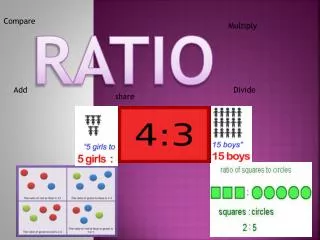
Ratio Control • Ratio control is applied when the control objective is to keep the ratio between two variables, often flows, at a certain value, a. • For example, in combustion, it is desired to control the fuel to air supply ratio, in order for the combustion to be as efficient as possible. This material on Ratio control is based on the following paper: Tore Hagglund. The Blend station: a new ratio control structure, Control Engineering Practice, 9, 1215–1220, (2001).
Ratio Control: Traditional Approach • Ratio control is normally solved as shown below.
Ratio Control: Traditional Approach • There are two control loops: the main loop consists of process P1and controller C1and the second loop, consisting of process P2 and controller C2 • Output y1is the main flow and the external set-point r1is the desired main flow. • It is attempted to control the flow y2 so that the ratio y2/y1= a. In the previous Figure, this is obtained using a Ratio station where set-point r2 is determined by r2 (t) = a y1(t)
Ratio Control: Traditional Approach • Provided the controllers have an integral action, the traditional ratio control approach will work in a steady-state, i.e. y1 = r1 and y2 = ay1. • However, during transients, the second flow y2 will always be delayed compared to the desired flow ay1. • The length of this delay is determined by the dynamics in the second loop. When set-point r1 is increasing, the delay causes an under-supply of the media corresponding to flow y2 ; and vice versa. • There are cases when it is important never to get any under-supply of one of the two media.
Ratio Control: Traditional Approach • We can conclude that using traditional Ratio stations, the desired ratio may be kept during a steady-state operation, but they fail to retain the desired ratio, a,during transient response. • This is a serious problem, since ratio control is normally applied to problems where the flows are supposed to vary and where steady-state conditions are uncommon.
Ratio Control: Second Approach • A second approach is to apply the Ratio station to set-point r1 instead of measurement signal y1. That is, set-point r2is determined by r2 (t)=ar1(t).
Ratio control: Second Approach • Now, the second flow is not necessarily delayed compared to the main flow as in the previous approach. • The transient behavior is determined by the dynamics in both loops. By tuning the controllers so that the loops get the same closed-loop dynamics, the ratio y2 = ay1 may be kept even during transients. • There is, however, a severe drawback with this method. The procedure is a kind of open-loop approach. If the dynamics in one of the loops change, so may the ratio y2 = ay1. Process dynamics often change in process control, mostly due to nonlinearities.
The Blend station • For this reason, a third approach is suggested that combines the advantages of the previous two methods. The author called it “the Blend station”.
The Blend station • In the Blend station, the secondary set-point is determined according to r2(t) = a ( γ r1(t) + (1- γ) y1(t) ). • Where the gain γis a weighting factor: - If γ = 0 the first method is used. - If γ= 1 the second method is used. • The gain γcan be properly adjusted according to the application.