Download
1 / 17
170 likes | 187 Views
Learn mechanical & electrical troubleshooting for AC equipment. Covers gages, refrigerants, gage manifold usage, gage connections, temperature & pressure readings, charging procedures, electrical troubleshooting, compressor issues, and circuit protectors.

E N D
41.1 Introduction • Troubleshooting ac equipment involves mechanical & electrical systems • Symptoms may overlap • Technicians must diagnose problems correctly - systematically
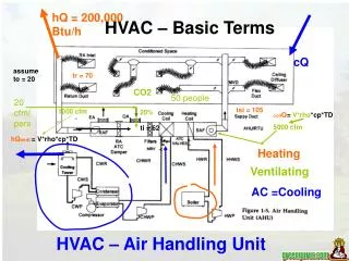
41.2 Mechanical Troubleshooting • Gages & thermometers used when doing mechanical troubleshooting • R-22 and 410A most common refrigerant used in ac equipment • R-22 t/p chart printed on each gage
Approaching temperature and Temperature difference • Air leaving the evaporator is about 17*-20* cooler than entering • Your split should be 20* for R-22 and 25* for 410A
41.4 Gage manifold usage • Displays low & high side pressures • Pressures are converted to saturation temps for evaporating refrigerant & condensing refrigerant • Two types of pressure connections: • Schrader valve, Service valve Note:Service valves can be used to isolate the refrigerant
41.4 When to Connect Gages • Gage manifolds not connected every time system serviced • Small amounts of refrigerant escape each time gages connected • Short gage hoses limit amount of refrigerant loss • Use isolation valve to limit loss- especially on liquid line
41.4 When to Connect Gages • Gage manifolds not connected every time system serviced • Small amounts of refrigerant escape each time gages connected • Short gage hoses limit amount of refrigerant loss • Use isolation valve to limit loss- especially on liquid line
41.6 Low Side Gage Readings • Used to compare actual evaporating pressure to normal evaporating pressure • Low side reading verifies refrigerant boiling at correct temp at current load condition • Standard efficiency systems usually have boiling temp ~30-35*F cooler than entering air temp at standard operating condition of 75*F return air with 50% RH • Space temp out of these ranges cause oversized load on evaporator
41.7 High Side Gage Readings • Used to check relationship of condensing refrigerant to ambient air temperature • Standard air cooled condensers no more than 30*F higher than AA • Check actual outside air temperature • High efficiency condensers operate at lower pressures & condensing temps • TD of 30*
41.8 Temperature Readings • Useful when checking performance of air conditioning equipment • Temps will vary from system to system • Common temps used for evaluation: Suction-line temperature Condenser outlet-line temperature Compressor discharge-line temperature
Temperature readings 90* summer day readings R22 coil temp 40* or 70psi (low side) condenser temp 125* or 275psi (high side) R410A coil temp 40* or 120psi (low side) condenser temp 125* or 400psi (high side)
41.9 Charging Procedures in Field Correct charge consists of enough refrigerant in: • Evaporator- Superheat • Suction line • Liquid line • Discharge line • Condenser- Subcooling
41.9 Charging procedures in field NOTE: under charge will cause high superheat and low subcooling Over charge will cause low superheat and high subcooling
41.10 Electrical Troubleshooting Volt, Ohms, Amps meter • Tech must know what readings should be • Control voltage stepped down to 24 volts • Begin any electrical troubleshooting by verifying that the power supply is energized • If the power supply voltage is correct, move on to the various components • Checking electrical circuits in parallel should be checked separately
41.11 Compressor Overload Problems • When compressor overload protector is open, touch motor housing to see if hot • The compressor can be cooled by running cold water over the top of it, ice bag it or by disconnecting it and allowing it to cool cool • Cooling compressor by running water over it may take 30 minutes or longer- usually longer
41.12 Compressor Electrical Checkup Introduction • Check the motor windings with ohmmeter • Refer to manufacturer's specifications for correct winding resistance values • Compressor may have: Shorted winding Open winding Grounded winding
41.13 Troubleshooting the Circuit Electrical Protectors – Fuses and Breakers • Compressors & fan motors have protection to guard from minor problems • Do not reset or replace tripped breaker or fuse without determining what caused it to trip or blow