Classical Lamination Theory W.rangsri
Definition of Composite Materials Fibers and Matrix Phases Composite Composition and Properties Manufacturing Processes Applications. Classical Lamination Theory W.rangsri. Intro. to Mechanics of Laminated Composite Materials Introduction to Composite Materials. Contents.


Classical Lamination Theory W.rangsri
E N D
Presentation Transcript
Definition of Composite Materials Fibers and Matrix Phases Composite Composition and Properties Manufacturing Processes Applications Classical Lamination TheoryW.rangsri Intro. to Mechanics of Laminated Composite Materials Introduction to Composite Materials
Contents • The Kirchhoff Hypothesis • Laminate Nomenclature • LaminateStrains and Displacements: The Kirchhoff Hypothesis • LaminateStrains • Laminate Stresses • Stress Distributions through the Thickness • Force and Moment Resultants • LaminateStiffness Matrix • LaminateStiffness: The ABD Matrix • Classification of Laminates • ElasticCouplings
Introduction • Understand • how laminatesresponse to load • how the fiber angles of the individuallayers influence laminateresponse • how the stacking arrangement of the layers influences the response • how changingmaterialproperties in a group of layers changes response • how the stresses are influenced by theseparameters
The Kirchhoff Hypothesis Laminate Nomenclature
The Kirchhoff Hypothesis Laminate Nomenclature
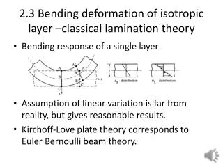
The Kirchhoff Hypothesis Laminate Strains and Displacements: The Kirchhoff Hypothesis • 1800s by Kirchoff • Greatlysimplifiedanalysis (accuratelypredict the response of beams, plate, and shells) • Hypothesisapply to other structures
The Kirchhoff Hypothesis Laminate Strains and Displacements: The Kirchhoff Hypothesis M: Applied moments q: Distributedappliedloads N: Inplaneloads P: Point loads Laminateis flat. All layer are perfectlybondedtogether.
The Kirchhoff Hypothesis Laminate Strains and Displacements: The Kirchhoff Hypothesis Kirchoffhypothesis assumes thatline AA’ remainsstraightand normalto the deformedgeometricmidplane and does not change length.
The Kirchhoff Hypothesis Laminate Strains and Displacements: The Kirchhoff Hypothesis Kirchoffhypothesis assumes thatline AA’ remainsstraight and normal to the deformedgeometricmidplane and does not change length.
: Rotation of ref. surface about y The Kirchhoff Hypothesis Laminate Strains and Displacements: The Kirchhoff Hypothesis z-x plane u°: Translation of point P° in x direction w°: Translation of point P° in z direction
: Rotation of ref. surface about x The Kirchhoff Hypothesis Laminate Strains and Displacements: The Kirchhoff Hypothesis y-z plane v°: Translation of point P° in y direction w°: Translation of point P° in z direction
The Kirchhoff Hypothesis Laminate Strains and Displacements: The Kirchhoff Hypothesis
The Kirchhoff Hypothesis Laminate Strains (small deformations, small dispalcements) Tensor shear strain = curvature of the ref. surface = inverse of the radius of curvature
The Kirchhoff Hypothesis Laminate Strains (small deformations, small dispalcements)
The Kirchhoff Hypothesis Laminate Strains (small deformations, small dispalcements)
The Kirchhoff Hypothesis Laminate Strains (small deformations, small dispalcements)
The Kirchhoff Hypothesis Laminate Strains (small deformations, small dispalcements) A small segment of a four-layer laminate (0.6 mm thick) deformed such that at a point P0 on the reference surface the extensional strain in the x direction is 1000 x 10^-6. The radius of curvature R0, of the reference surface, is 0.2 m.
The Kirchhoff Hypothesis Laminate Stresses • CLT => each point within the vol. of a laminateis in a state of plane stress. • the stresses varywith z • the strainsvarywith z • reducedstiffnessesvarywith z
CLT Example 1 [0/90]S graphite-epoxy laminate (0.6 mm) subjectedto known The Kirchhoff Hypothesis Stress Distributions through the Thickness
The Kirchhoff Hypothesis Stress Distributions through the Thickness
CLT Example 1 [0/90]S graphite-epoxy laminate (0.6 mm) subjectedto known The Kirchhoff Hypothesis Stress Distributions through the Thickness
CLT Example 1 [0/90]S graphite-epoxy laminate (0.6 mm) subjectedto known The Kirchhoff Hypothesis Stress Distributions through the Thickness
CLT Example 1 [0/90]S graphite-epoxy laminate (0.6 mm) subjectedto known The Kirchhoff Hypothesis Stress Distributions through the Thickness 0° 90° 90°
CLT Example 1 [0/90]S graphite-epoxy laminate (0.6 mm) subjectedto known The Kirchhoff Hypothesis Stress Distributions through the Thickness 0°
CLT Example 1 [0/90]S graphite-epoxy laminate (0.6 mm) subjectedto known The Kirchhoff Hypothesis Stress Distributions through the Thickness 90°
CLT Example 1 [0/90]S graphite-epoxy laminate (0.6 mm) subjectedto known The Kirchhoff Hypothesis Stress Distributions through the Thickness 0° 90°
CLT Example 1 [0/90]S graphite-epoxy laminate (0.6 mm) subjectedto known The Kirchhoff Hypothesis Stress Distributions through the Thickness aluminum
CLT Example 1 [0/90]S graphite-epoxy laminate (0.6 mm) subjectedto known The Kirchhoff Hypothesis Stress Distributions through the Thickness
CLT Example 1 [0/90]S graphite-epoxy laminate (0.6 mm) subjectedto known The Kirchhoff Hypothesis Stress Distributions through the Thickness 0°
CLT Example 1 [0/90]S graphite-epoxy laminate (0.6 mm) subjectedto known The Kirchhoff Hypothesis Stress Distributions through the Thickness 90°
CLT Example 1 [0/90]S graphite-epoxy laminate (0.6 mm) subjectedto known The Kirchhoff Hypothesis Stress Distributions through the Thickness 0° 90°
CLT Example 1 [0/90]S graphite-epoxy laminate (0.6 mm) subjectedto known The Kirchhoff Hypothesis Stress Distributions through the Thickness
CLT Example 1 [0/90]S graphite-epoxy laminate (0.6 mm) subjectedto known The Kirchhoff Hypothesis Stress Distributions through the Thickness
CLT Example 1 [0/90]S graphite-epoxy laminate (0.6 mm) subjectedto known The Kirchhoff Hypothesis Stress Distributions through the Thickness
CLT Example 1 [0/90]S graphite-epoxy laminate (0.6 mm) subjectedto known The Kirchhoff Hypothesis Stress Distributions through the Thickness 0° 90°
CLT Example 1 [0/90]S graphite-epoxy laminate (0.6 mm) subjectedto known The Kirchhoff Hypothesis Stress Distributions through the Thickness 0° 90°
CLT Example 1 [0/90]S graphite-epoxy laminate (0.6 mm) subjectedto known The Kirchhoff Hypothesis Stress Distributions through the Thickness aluminum
The Kirchhoff Hypothesis Force and Moment Resultants
The Kirchhoff Hypothesis Force and Moment Resultants
CLT Example 1 [0/90]S graphite-epoxy laminate (0.6 mm) subjectedto known The Kirchhoff Hypothesis Force and Moment Resultants
CLT Example 1 [0/90]S graphite-epoxy laminate (0.6 mm) subjectedto known The Kirchhoff Hypothesis Force and Moment Resultants
CLT Example 2 [0/90]S graphite-epoxy laminate (0.6 mm) subjectedto known The Kirchhoff Hypothesis Force and Moment Resultants
CLT Example 2 [0/90]S graphite-epoxy laminate (0.6 mm) subjectedto known The Kirchhoff Hypothesis Force and Moment Resultants