Download
1 / 17
210 likes | 533 Views
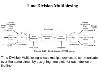
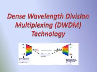
Dense Wavelength Division Multiplexing (DWDM) Technology. Introduction:-.

E N D
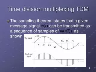
Introduction:- Due to the internet boom the demand for transmission capacity is growing rapidly. Optical data transmission is the key to meet this requirement. Principally, there are three possibilities to increase the transmission capacity: space division multiplex (deployment of further transmission cables), time domain multiplex (increasing the data rate) and dense wavelength division multiplex (transmitting several channels via one Single mode fiber).As in the wavelength range of 1280nm to 1650nm the technically useable bandwidth of the single mode fiber is 53THz, it is only consequent to take advantage of this large frequency range by using transmitters of different wavelengths.
Evolution of DWDM Technology 64-160 channels 25-50 GHz spacing 15-40 channels 100-200 GHz spacing Dense WDM, integrated systems with network management add-drop functions 2-8 channels passive WDM 200-400 GHz spacing WDM components parts 2 channels wideband WDM 1310nm, 1550nm
Basic components and operations • Transmitting Side • Lasers with precise stable wavelengths • Optical Multiplexers • On the Link • Optical fiber • Optical amplifiers • Receiving Side • Photo detectors • Optical De multiplexers • Optical add/drop multiplexers
Optical fiber The main job of optical fibers is to guide light waves with a minimum of attenuation (loss of signal). Optical fibers are composed of fine threads of glass in layers, called the core and cladding, that can transmit light at about two-thirds the speed of light in a vacuum. Though admittedly an oversimplification, the transmission of light in optical fiber is commonly explained using the principle of total internal reflection. With this phenomenon, 100 percent of light that strikes a surface is reflected. By contrast, a mirror reflects about 90 percent of the light that strikes it.
Light Sources and Detectors Light emitters and light detectors are active devices at opposite ends of an optical transmission system. Light sources, or light emitters, are transmit-side devices that convert electrical signals to light pulses. The process of this conversion, or modulation, can be accomplished by externally modulating a continuous wave of light or by using a device that can generate modulated light directly. Light detectors perform the opposite function of light emitters. They are receive-side opto-electronic devices that convert light pulses into electrical signals.
Erbium-Doped Fiber Amplifier • Eliminates O-E-O conversions • More effective than electronic repeaters • Isolator prevents reflection • Light at 980nm or 1480nm is injected via the pump laser • Gains ~ 30dB; Output Power ~ 17dB
Multiplexers and Demultiplexers Because DWDM systems send signals from several sources over a single fiber, they must include some means to combine the incoming signals. This is done with a multiplexer, which takes optical wavelengths from multiple fibers and converges them into one beam. At the receiving end the system must be able to separate out the components of the light so that they can be discreetly detected. Demultiplexers perform this function by separating the received beam into its wavelength components and coupling them to individual fibers. Demultiplexing must be done before the light is detected, because photo detectors are inherently broadband devices that cannot selectively detect a single wavelength.
Optical Add/Drop Multiplexers Between multiplexing and demultiplexing points in a DWDM system, as shown in Figure , there is an area in which multiple wavelengths exist. It is often desirable to be able to remove or insert one or more wavelengths at some point along this span. An optical add/drop multiplexer (OADM) performs this function. Rather than combining or separating all wavelengths, the OADM can remove some while passing others on. OADMs are a key part of moving toward the goal of all-optical networks.
The transponder accepts input in the form of standard single-mode or multimode laser. The input can come from different physical media and different protocols and traffic types. 2. The wavelength of each input signal is mapped to a DWDM wavelength. 3. DWDM wavelengths from the transponder are multiplexed into a single optical signal and launched into the fiber. The system might also include the ability to accept direct optical signals to the multiplexer; such signals could come, for example, from a satellite node. 4. A post-amplifier boosts the strength of the optical signal as it leaves the system (optional). 5. Optical amplifiers are used along the fiber span as needed (optional). 6. A pre-amplifier boosts the signal before it enters the end system (optional). 7. The incoming signal is demultiplexed into individual DWDM lambdas (or wavelengths). 8. The individual DWDM lambdas are mapped to the required output type (for example, OC-48 single-mode fiber) and sent out through the transponder
Drawbacks:- • Dispersion • Chromatic dispersion • Polarization mode dispersion • Attenuation • Intrinsic: Scattering, Absorption, etc. • Extrinsic: Manufacturing Stress, Environment, etc. • Four wave mixing • Non-linear nature of refractive index of optical fiber • Limits channel capacity of the DWDM System
Conclusion:- • Robust and simple design • Works entirely in the Optical domain • Multiplies the capacity of the network many fold • Cheap Components • Handles the present BW demand cost effectively • Maximum utilization of untapped resources • Best suited for long-haul networks
A Presentation by:- Jesina John J.Preeti Akshita Bhatnagar Eena Michael Lal Thank You….