Download
1 / 44
440 likes | 459 Views
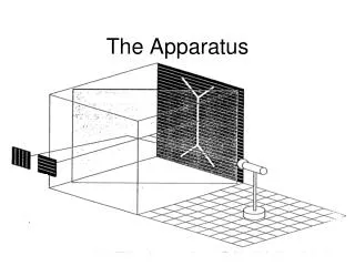
Selected Technical Aspects of the Qweak Apparatus (stuff we need to write down for the Moeller experiment before we forget). D.J. Mack (TJNAF) PAVI11 Roma, Italia. DOE, NSF, NSERC. Spectrometer. Spectrometer.

E N D
Selected Technical Aspects of the Qweak Apparatus (stuff we need to write down for the Moeller experiment before we forget) D.J. Mack (TJNAF) PAVI11 Roma, Italia DOE, NSF, NSERC
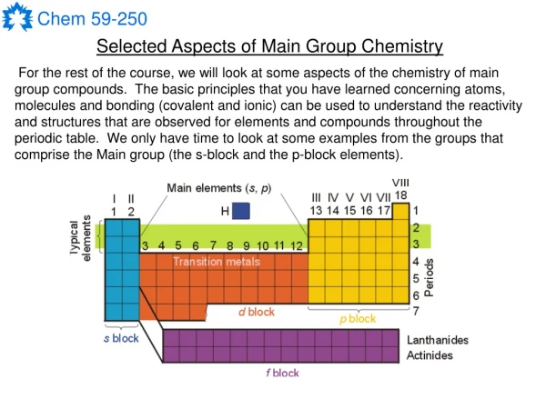
Spectrometer The Qweak spectrometer has to isolate elastic e+p events at small angles, with the largest acceptance possible, without tracking detectors. (A new particle traverses each detector approximately every nsec.) No ferromagnetic materials can be used, so a brute-force electromagnet was required. (The PC asymmetry for pol e+ pol e scattering is a billion times larger than our level of comfort.) • Toroidal magnets seem an inefficient way to bend particles (they immediately curve out of the high field regions, wasting much of the volume). But • the 1/R field bends small scattering angles more than large ones, thus focusing the bundle of angles, and • a 15 degree average bend is just enough, with our highly optimized collimation, to minimize background. Target Detector Collimation/ Shielding Toroidal Magnet
Simple Coils Are Not Simple The conductor xsect was 2”x2”. Initially, winding even this simple race-track design without warping was a challenge. Non-magnetic Silicon-Bronze bolts were used throughout the experiment. One frustrated wag working on the main detector compared their strength to “warm cheese”. Occasionally, the conductor has to be spliced. A tough bit of plumbing. Without good quality control in the brazing, the joints would leak when warm and pressurized. Si-Bronze bolts also showed an astonishing tendency to “relax” on their way from uptight Boston to laid back Virginia.
QTOR in Hall C After an enormous effort by TRIUMF/MIT-Bates/SigmaPhi, the coils and support structure were delivered and re-assembled at Jlab. Isn’t she gorgeous? She has some few mm imperfections in alignment (who doesn’t?), resulting in a 4 kG-cm field along the beamline which bends the low energy tail of the straggled beam into downstream vacuum seals.
Front Shield Wall Motivation • Safely dump gamma rays and inelastic electrons before they enter the detector hut. • Reduce the solid angle for accepting the “glow” from the Hall and beamline. Inelastics (missing the detector) Elastics Blue – photons Red – electrons
Shield Wall CAD Side view, 8 beams The design required apertures for 8 beam envelopes large enough to provide some shielding while doing no harm (i.e., minimal showers from scraping) Side view close-up, 1 beam Top view close-up, 1 beam Assembled monolith tolerances were ±1 cm.
Gotcha (almost) The detailed shield wall design was done last. Given how little space remained, simulations showed the concrete density had to be increased from standard to high density 2.4 g/cm3 2.7 g/cm3 High density concrete is straightforward as long as you dump in scrap steel or iron oxides. But the steel is magnetic, and natural iron oxides like hematite (Fe2O3) are often heavily contaminated with magnetite (Fe3O4). Lesson learned: None. With most of Jlab’s designers working on 12 GeV projects, we often had to make do with a single designer.
Fabrication and Assembly • The non-magnetic material specification came at a high cost: • Stainless steel rebar • (very dear but affordable, thanks to the ubiquity of hospital MRI’s) • Barite-loading (BaSO4) for high density • (the insoluble stuff of the “barium milkshake”) To be able to install the structure, it was poured “lying down” in Lego-like pieces, taken apart, then reassembled in Hall C. This was Jlab’s most complex concrete project for its size. Our civil engineer, Suresh Chandra, enjoyed the challenge.
Focal Plane Our azimuthal acceptance is about 50%. It appears larger here because azimuthal defocusing enlarges the beam spots to 2m length. Inelastics Elastics Separation of elastics from inelastics is excellent.
Requirements Implementation • Spectrosil 2000 has the following properties: • Rad-hard to > Mrad • Insensitive to gamma rays below 0.6 MeV • Very low scintillation or luminescence. “Optical Properties of the DIRC Fused Silica Cherenkov Radiator”, Cohen-Tanugi et al, NIM A 515 (2003) 680-700. • Eight detectors with sensitive area • 200 x 18 cm2 • Rad-hard to at least 100 kRad • Relatively insensitive to backgrounds • Additional extra noise (eg, due to poor energy resolution or shower fluctuations) • Ability to operate in CW or pulsed mode. • Modest non-linearity. • Eight Cerenkov detectors with sensitive volume 200 x 18 x 1.25 cm3 • Resolution compromised by large collection area, but with 25 Angstroms (rms) polish, is good enough at ~16 pe’s/track. • ET 9390KB 5” PMTs can operate in either mode by simply changing the gain. • To handle high light levels, the PMTs use high conductivity S20 photocathodes.
Manitoba Radiator Modules • Supports fused silica and glue joints in any orientation • Minimize (in)showering • (Al frame, thin windows, gap between radiator and frame) • Magnetic shielding for the 5” PMT (earth’s field only) • Easy conversion from current to event mode by replacing the base • Light tight • Electrical feed-thrus for LEDs. Gap between quartz and frame reduces in-showering. Quartz supports are thin on upstream side. Magnetic shield and PMT inside housing
JlabExo-Skeletons Manitoba radiator modules (physicist responsibility) were installed in a strong, stiff Jlab exo-skeleton suitable for carrying Pb shielding and pre-radiators (engineering and safety responsibility). Each module carries 200 lbs (90 kg) of Pb bricks to provide limited shielding for PMTs. (Pre-radiators would double that.)
Main Detector R&D Issues Resolved(several man-years) Learned to make optical transmission measurement with 0.1% accuracy using a Jlab spectrophotometer. Measured with high significance the very weak scintillation in artificial fused silica using 5 keV x-rays and an optical chopper wheel. • PMT linearity measurements: • 2 LED: one DC load, one AC signal • (gives nonlinearity in 0 Hz limit) • 3 LED: one DC load, two AC signals • (mixing f1±f2 is proportional to nonlinearity) Learned to prime and glue ultra-smooth fused silica surfaces using Shin-Etsu Silicones 406.
Witness Plates These are large glass slides located on the downstream face of the detectors. The idea was to burn in the image of the beam envelope as a crude check on the average position of beam envelopes in all octants. Slow-w-w technique, but agrees with RIII tracking that the 8 beam envelopes are in the right place. Also justifies to my Project Manager why we had to spend 1/3 M$ for Spectrosil 2000 (which shows no visible damage).
TRIUMF Custom Low Noise Electronics Electronic noise is over two orders of magnitude smaller than counting statistics noise of electron tracks. battery signal VME integrator – 18 bit ADC sampling at 500 kHz FPGA sums 500 samples into one data word same resolution as a 26 bit ADC This permits us to check for ppb-level false asymmetries from cross-talk in only one shift.
Diffuse Backgrounds from Beamline Experiment started with 1.25cm fused silica radiators and no pre-radiators. Correlated fluctuations in the detectors big enough to see on a scope suggested an O(10)% dilution from soft background from beamline. An integrating experiment like Qweak doesn’t have to worry about pile-up, dead-time, or random coincidences. The downside is that there’s no way to improve Signal/Bkg ratios offline. Our total background uncertainty budget was ~0.5%. We had to get rid of it. Detector’s eye view.
Wuzzup? Beamline collimator snapshots with a large (12mm x 12mm raster), triggered on shieldhouse background. Per design, ~0.5% of the straggled primary beam is dumped on our beamline-defining collimator, making lots of neutral background. This is well-shielded, but … The detectors are “thin”, the power dissipated in them is only abut 1E-8 that dumped on the beamline. Line of sight shielding wasn’t enough: troublesome neutrals from the beamline could still bounce and make it to the detectors. Target out. The lower contrast with “Target In” is a nice demonstration that detector background is being produced by electrons scattering to the beamline. Target in.
Step 1. Plug Shielding Gaps “RII” “RI” Beamline inside QTOR • Gaps in beamline shielding were recognized and plugged. Lessons learned: • Tour the installation frequently before oversights become buried. • Don’t assume the as-built will exactly match the design. • Need a hero(ine) to update the monte carlo with as-built information.
Step 2. Install Pre-radiators • Plan B: 2 cm thick Pb pre-radiators • Near 1 GeV, a shower-max preradiator can • amplify the signal by a factor of ~7, and • attenuate few MeV gamma rays by ~3 • for a net improvement in Signal/Background of ~20. This was Plan B because it trades off a background issue for a statistical one: shower fluctuations at this relatively low beam energy broaden the statistical width by 10%.
Step 3. Wrap the Beampipe Background studies with Pb bricks tracked down a beamline glow (pipe ID just a hair too small?) which we killed with a 5cm thick Pb donut. Beamline background during most of Run I was ~0.2%. Detector’s eye view. ?
Summary • Non-magnetic material specifications added to cost and headaches in ways that were sometimes completely unexpected. • Every physicist knows the residual field on the axis of a symmetric torus is zero. Unfortunately, not only EW symmetry is broken … • During the installation phase, designers and simulation experts need to be frequently kicked out of their offices to face the real world. • Spectrosil 2000 is a fantastic material for rad-hard Cerenkov detectors. We stand on the shoulders of the giants of the BaBar DIRC group. • Signals are easy to calculate. Backgrounds are harder. If the backgrounds turn out to be too large, it’s important to have a Plan B ready. • Problem-solving must be paid for in a coin of time, space, money, and people. Keep a hefty surplus of all four.
The Q-weak Collaboration W&M meeting A. Almasalha, D. Androic, D.S. Armstrong, A. Asaturyan, T. Averett, J. Balewski, R. Beminiwattha, J. Benesch, F. Benmokhtar, J. Birchall, R.D. Carlini1 (Principal Investigator), G. Cates, J.C. Cornejo, S. Covrig, M. Dalton, C. A. Davis, W. Deconinck, J. Diefenbach, K. Dow, J. Dowd, J. Dunne, D. Dutta, R. Ent, J. Erler, W. Falk, J.M. Finn1*, T.A. Forest, M. Furic, D. Gaskell, M. Gericke, J. Grames, K. Grimm, D. Higinbotham, M. Holtrop, J.R. Hoskins, E. Ihloff, K. Johnston, D. Jones,M. Jones, R. Jones, K. Joo, E. Kargiantoulakis, J. Kelsey, C. Keppel, M. Kohl, P. King, E. Korkmaz, S. Kowalski1,J. Leacock, J.P. Leckey, A. Lee, J.H. Lee, L. Lee, N. Luwani, S. MacEwan, D. Mack, J. Magee, R. Mahurin, J. Mammei, J. Martin, M. McHugh, D. Meekins, J. Mei, R. Michaels, A. Micherdzinska, A. Mkrtchyan, H. Mkrtchyan, N. Morgan, K.E. Myers, A. Narayan, Nuruzzaman, A.K. Opper, S.A. Page1, J. Pan, K. Paschke, S.K. Phillips, M. Pitt, B.M. Poelker, J.F. Rajotte, W.D. Ramsay, M. Ramsey-Musolf, J. Roche, B. Sawatzky, T. Seva, R. Silwal, N. Simicevic, G. Smith2, T. Smith, P. Solvignon, P. Souder, D. Spayde, A. Subedi, R. Subedi, R. Suleiman, E. Tsentalovich, V. Tvaskis, W.T.H. van Oers, B. Waidyawansa, P. Wang, S. Wells, S.A. Wood, S. Yang, R.D. Young, S. Zhamkochyan, D. Zou 1Spokespersons *deceased 2Project Manager
Ancillary Physics Bkg Measurements Aluminum target windows - elastic +QE ~3% dilution of signal, ~20% correction N→Δ asymmetry ~0.1% dilution, ~1% correction Parity conserving, transverse asymmetry on LH2. A very small correction. Est’d error
LH2 Data Quality Convergence to mean ~rms/sqrt(N). Width is a very important FOM! • At 165 μA, total detected rate is 5.83 GHz. • Pure counting statistics: 215 ppm • + detector shower fluctuations 232 ppm • + current normalization and target 235 ppm • Width is understood and about 10% above c.s. 0.8 ppm statistical error in only 6.5 minutes at 165 μA The electron polarity may be reversed every 1 msec by electronic means. An Insertable Half Wave Plate (IHWP) optically flips the polarity before every 8 hour “slug”. The signal must reverse sign. unregressed, uncorrected, blinded
Window View, midline, RMD Moeller fountain lintel Collimator 3 “RII” Coil holder Coil holder beamline
Window View, midline, Rnominal Direct view: Potential beamline hot spots to MD “RII” “RI” (no longer visible) Beamline inside QTOR
Averaging of Digitization Noise • The 18 bit ADCs have ~0.5 LSB rms noise per sample. • This is reduced by averaging ~500 samples per integration. • This will only work if raw signal spreads over enough channels. • Assuming equivalent noise bandwidth 47 kHz (f3db= 30 kHz) and 18 bit ADC at mid range: • condition Q rms noise before channels channels • (e) integration () (FWHM) • beam ON 50,000 69 mV 1420 3339 • LED test 1,000 9.8 mV 201 472 • battery test 1 0.31 mV 6.3 15 • So this is OK even for very quiet signals.
Collimator 1 Plug Plugging a collimator 1 octant would tell how much background is coming from other octants + downstream of the plugged octant (shaded yellow). Measurements have been taken. Perhaps Paulo can design some sort of slider. Not a short-term project. Looking upstream at octant 6
Collimator 2 Plug Overview Plugging a collimator 2 octant would tell us how much background is coming from other octants + downstream of the plugged octant (shaded yellow). Looking upstream at 6 o’clock octant Same from beam right
Collimator 2 Plug Detail Efficacy: 3” Pb 13 X0 thickness and >2Rmoliere border will stop primary electrons cold. Together with the 4” of Pb in the lintel, this may be sufficient to stop the gamma rays as well. If GEANT indicates too much gamma ray leakage (preliminary results OK), more Pb could be added between the legs of the “Λ” which supports RII. Front view Side view ALARA considerations: 4% Al (us) running suggests a beam- off dose rate O(100) mR/hour. Because the vendor took a vacation in August like the rest of us, we may not receive the plug in time to install/practice before the run. Elastic electrons
RII Neutral Background Study on LH2 Target 7753 LH2 3x3 140 muA MD7neg 34.4 mV/muA MD7pos 39.3 mV/muA BRII + Bothers ~ 0.45% [RII plugged] Background dropped > 65% Bothers ≤ 0.18% [RII plugged + 12” lead] BRII ≥ 0.27% 38 RII others
Use of a Pre-radiator: Trade-offs A shower-max preradiator could increase Signal/Background. But at what cost? Excess noise increases to 12%. Potential for increasing S/B > 30 A 2 cm Lead sheet in front of our quartz bars would increase S/B by > 30, but would require 390 additional hours, and increase the radiation dose to 3 MRad. Won’t need this if backgrounds are only 1%.
Dose Estimate to Radiators Assuming a thin radiator and a rate of 800 MHz distributed uniformly over an area of 200cm x 12cm for 2500 hours: Energy Flow [MeV/(g/cm2)] = 8x108Hz x 2.4MeV/(g/cm2) x 2500 hrs x 3600sec/hr = 1.7x10¹⁶ MeV/(g/cm2) Area [cm2] = 200cm x 12 cm = 2400 cm2 Dose [MeV/g] = Energy Flow/Area = 1.7x10¹⁶MeV/(g/cm2)/2400cm2 = 7.1x10¹² MeV/g Dose [Rad] = 7.1x10¹²MeV/g x (100 Rad/6.24x109 MeV/g) = 1.1x10⁵ Rad • Average dose is about 100 kRad • Allowing for nonuniformities, showering, we should assume 300 kRad. • If a pre-radiator is used, for E’ = 1 GeV this will increase by a factor of ~7.
Tilt Angle Optimization Because we are collecting light from a Cerenkov cone by total internal reflection, the light collection varies in non-obvious ways on the bar tilt angle. Excess noise and uniformity of light collection were examined. Excess noise varied only by 1.5%. Not a driving issue. When the bars are oriented close to a vertical plane, the uniformity is optimized.This is important.
Bar Thickness Optimization We optimized the thickness of the bars. With increasing thickness, greater light production competes with greater fluctuations from showering. The predicted optimum is near 1 cm.