Download
1 / 26
380 likes | 607 Views
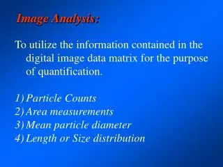
Image Analysis. Preprocessing Arithmetic and Logic Operations Spatial Filters Image Quantization. Arithmetic and Logic Operations. Arithmetic and logic operations are often applied a preprocessing steps in image analysis in order to combine images in various way.

E N D
Image Analysis Preprocessing Arithmetic and Logic Operations Spatial Filters Image Quantization
Arithmetic and Logic Operations • Arithmetic and logic operations are often applied a preprocessing steps in image analysis in order to combine images in various way. • Addition, subtraction, division and multiplication comprise the arithmetic operation, while AND , OR, and NOT make up the logic operations. • These operation performed on two image , except the NOT logic operation which require only one image, and are done on a pixel by pixel basis. (see example 3.2.2 for add images)
Figure 3.2-6 Image Addition Examples. This example shows one step in the image morphing process where an increasing percentage of the second image is slowly added to the first, and a geometric transformation is usually required to align the images. a) first original, b) second original, c) addition of images (a) and (b). This example shows adding noise to an image which is often useful for developing image restoration models. d) original image, e) Gaussian noise, variance = 400, mean = 0, f) addition of images (d) and (e). b) a) c) e) d) f)
Subtraction • Subtraction of two image is often used to detect motion. • Consider the case where nothing has changed in a scene; the image resulting from subtraction of two sequential image is filled with zeros - a black image. • If something has moved in the scene, subtraction produce a nonzero result at the location of movement.
a) b) c) d) e) f) Figure 3.2-7 Image Subtraction a) Original scene, b) same scene later, c) subtraction of scene a from scene b, d) the subtracted image with a threshold of 50, e) the subtracted image with a threshold of 100, f) the subtracted image with a threshold of 150. Theoretically, only image elements that have moved should show up in the resultant image. Due to imperfect alignment between the two images, other artifacts appear. Additionally, if an object that has moved is similar in brightness to the background it will cause problems – in this example the brightness of the car is similar to the grass.
Subtraction • Medical imaging often uses this type of operation to allow the doctor to more readily see changes which are helpful in the diagnosis. • The technique is also used in law enforcement and military applications; for example, to find an individual in a crowd or to detect changes in a military installation.
Multiplication n Division • used to adjust the brightness of an image. • is done on a pixel by pixel basis and the options are to multiply or divide an image by a constant value, or by another image. • Multiplication of the pixel value by a value greater than one will brighten the image (or division by a value less than 1), and division by a factor greater than one will darken the image (or multiplication by a value les than 1). • Brightness adjustment by a constant is often used as a preprocessing step in image enhancement and is shown in Figure 3.2.8.
Figure 3.2-8 Image Division. a) original image, b) image divided by a value less than 1 to brighten, c) image divided a value greater than 1 to darken a) b) c)
Logic operations • The logic operations AND, 0R and NOT operate in a bit-wise fashion on pixel data. • Example 3.2.3 • performing a logic AND on two images. Two corresponding pixel values are 11110 in one image and 8810 in the second image. The corresponding bit string are: 11110 = 011011112 88 = 010110002 011011112 AND 010110002 010010002
The Iogic operations AND and OR are used to combine the information in two images. • This may be done for special effects but a more useful application for image analysis is to perform a masking operation. • AND and OR can be used as a simple method to extract a ROI from an image.
For example, a white mask ANDed with an image will allow only the portion of the image coincident with the mask to appear in the output image, with the background turned black; and a black mask ORed with an image will allow only the part f the image corresponding to the black mask to appear in the output image, but will turn the return of the image white. • This process is called image masking
Figure 3.2-10 Image Masking. a) Original image, b) image mask for AND operation, c) Resulting image from (a) AND (b), d) image mask for OR operation, created by performing a NOT on mask (b), e) Resulting image from (a) OR (d). b) c) a) e) d)
Figure 3.2-11 Complement Image – NOT Operation. a) Original, b) NOT operator applied to the image b) a)
Spatial Filters • typically applied for noise mitigation or to perform some type of image enhancement. • The operators are called spatial filters since operate on the raw image data in the (r, c) space, the spatial domain. • operate on the image data by considering small neighborhood in an image, such as 3 x 3, 5 x 5, etc., and returning a result based on a linear or nonlinear operation; moving sequentially across and down the entire image.
Three types of filter discussed 1) mean filters, (2) median filter and (3) enhancement filter • The first two are used primarily to deal with noise in images, although they may also be used for special applications. • a mean filter adds a “softer “ look to an image (3.2.12). • The enhancement filters highlight edges and detail within the image.
Figure 3.2-12 Mean Filter. a) Original image, b) mean filtered image, 3x3 kernel. Note the softer appearance. b) a)
Many spatial filters are implemented with convolution mask . • Since, a convolution mask operation provides a result that is a weighted sum of the values of a pixel and it neighbors - linear filter. • One interesting aspect of convolution masks is that the overall effect can be predicted based on their general pattern.
For example, if the coefficients of the mask sum to one, the average brightness of the image will be retained. • if the coefficients sum to zero, the average brightness will be lost and will return a dark Image. • Furthermore, if the coefficient are alternating positive and negative, the mask is a filter that will sharpen an image; if the coefficients are all positive, it is a filter that will blur the image.
Mean filters • The mean filters are essentially averaging filters. • They operate on local group of pixel called neighborhoods, and replace the center pixel with an average of the pixel in this neighborhood. • This replacement is done with a convolution mask such as the following 3 x 3 mask: The result is normalized by multiplying by 1/9,
Median filter • The median filter is a nonlinear filter. • A nonlinear filter has a result that cannot be found by a weighted sum of the neighborhood pixels, such as done with a convolution mask. • median filter operates on a local neighborhood. • After the size of the local neighborhood is defined, the center pixeI is replaced with the median, or middle, value present among its neighbors, rather than by their average. (example 3.2.4) • used a neighborhood of any size, but 3 x 3,5 x 5 and 7 x 7
Figure 3.2-13 Median Filter. a) Original image with added salt-and-pepper noise, b) Median filtered image using a 3x3 mask b) a)
Enhancement filters • are linear filters, implemented with convolution masks having alternating positive and negative coefficients, so they will enhance image details. • Many enhancement filter can be defined, here we include Laplacian-type and difference filters. • Three 3 x 3 convolution masks for the Laplacian-type filter are: FILTER 1 FILTER 2 FILTER 3
The difference filters, also called emboss filter, will enhance detail in the direction specific to the mask selected. • There are four primary difference filter convolution mask, corresponding to lines in the vertical, horizontal, and two diagonal direction VERTICAL HORIZONTAL DIAGONAL2 DIAGONAL1
Figure 3.2-14 Enhancement Filters. a) Original image, b) image after laplacian filter, c) contrast enhanced version of laplacian filtered image, compare with (a) and note the improvement in fine detail information, b) c) a)
d) result of a difference (emboss) filter applied to image (a), e) difference filtered image added to the original, f) contrast enhanced version of image (e). e) f) d)
Image Quantization • is the process of reducing the image data by removing some of the detail information by mapping groups of data points to a single point. • can be done to either the pixel values themselves, I(r, c), or to the spatial coordinates, (r, c). • Operation on the pixel values is referred to as gray level reduction, while operating on the spatial coordinates called spatial reduction.