Download
1 / 62
620 likes | 740 Views
This guide details the essential steps for selecting, installing, and maintaining Programmable Logic Controllers (PLCs). It covers crucial criteria such as I/O capacity, memory size, types of inputs/outputs, scan times, and software languages. With a focus on understanding the controlled process, vendor selection, and ladder logic planning, it ensures effective decision-making. Additional insights are provided on future system expansions and support considerations for robust industrial automation. Mastering these aspects will lead to enhanced operational efficiency and system reliability.

E N D
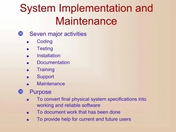
6.0 SELECTING, INSTALLING, MAINTENANCE & TROUBLESHOOTING PLC SYSTEM
After the planning phase of the design, the equipment can be ordered. This decision is usually based upon the required inputs, outputs and functions of the controller. The first decision is the type of controller; rack, mini, micro, or software based. This decision will depend upon the basic criteria listed below. • • Number of logical inputs and outputs. • • Memory - Often 1K and up. Need is dictated by size of ladder logic program. A ladder element will take only a few bytes, and will be specified in manufacturers documentation. • • Number of special I/O modules - When doing some exotic applications, a large number of special add-on cards maybe required. • • Scan Time - Big programs or faster processes will require shorter scan times. And, the shorter the scan time, the higher the cost. Typical values for this are 1 microsecond per simple ladder instruction • • Communications - Serial and networked connections allow the PLC to be programmed and talk to other PLCs. The needs are determined by the application. • • Software - Availability of programming software and other tools determines the programming and debugging ease. INTRODUCTION
The process of selecting a PLC can be broken into the steps listed below. • 1. Understand the process to be controlled • List the number and types of inputs and outputs. • • Determine how the process is to be controlled. • Determine special needs such as distance between parts of the process. • 2. If not already specified, a single vendor should be selected. Factors that might be considered are : • • Manuals and documentation • • Support while developing programs • • The range of products available • Support while troubleshooting • • Shipping times for emergency replacements • • Training • • The track record for the company • Business practices (billing, upgrades/obsolete products, etc.) • 3. Plan the ladder logic for the controls. • 4. Count the program instructions and enter the values into the sheets. Use the instruction times and memory requirements for each instruction to determine if the PLC has sufficient memory, and if the response time will be adequate for the process. INTRODUCTION
6.1 EXPLAIN PLC SELECTION PROCEDURE 6.1.1 Define input/output capacity: • The number of connection terminal at PLC I/O unit • Including local expansion & I/O network. • The total of Discrete vs Analog Input / Output Unit Specifications
6.1 EXPLAIN PLC SELECTION PROCEDURE 6.1.2 Define types of input / output: • Every programmable logic controller must have some means of receiving and interpreting signals from real-world sensors such as switches, and encoders, and also be able to effect control over real-world control elements such as solenoids, valves, and motors. • This is generally known as input/output • To select the I/O, must know; • Types of supply connected?– AC/DC • Switching technique? – Relay(normal condition)/Transistor(fast condition)/ AC(High voltage) • The I/O Unit has two type; i- Discrete I/O: ii- Analog I/O
i- Discrete I/O: • A “discrete” data point is one with only two states on & off. • Digital I/O modules have digital I/O circuits that interface to on/off sensors such as push-button and limit switches and on/off actuators such as motor starters & pilot lights • Digital I/O modules cover electrical ranges from 5 to 276 V AC or DC, and relay contact output modules are available for ranges from 0 to 276 V AC or 0 to 175 V DC.
ii- Analog I/O • Analog I/O modules perform the required A/D and D/A conversions using up to 16-bit resolution. • A range of analog signal levels can be accommodated, including standard analog inputs and outputs and direct thermocouple and RTD temperature inputs • Analog I/O is commonly available for modular PLCs for many different analog signal types, including: • Voltage (0 to 10 volt, 0 to 5 volt) • Current (0 to 20 mA, 4 to 20 mA) • Thermocouple (mV) • RTD (mV) • Strain gauge (mV)
6.1 EXPLAIN PLC SELECTION PROCEDURE 6.1.3 Define memory size: • The ability to store a program in the PLC. • 1K, 6K, 8K, 12K, 14K CPU unit specifications
6.1 EXPLAIN PLC SELECTION PROCEDURE 6.1.4 Describe types of software language: • Ladder diagram – most popular • Instruction list • Structured text • Sequential function chart • Function block diagram
6.1 EXPLAIN PLC SELECTION PROCEDURE 6.1.5 Describe future system expansion: • Today, the industry control system having a transformation from traditional control method to automation control system. • Most popular automation system: • Flexible Manufacturing System (FMS) • Computer Integrated Manufacturing (CIM). • PLC become the main agent for the automation system.
6.1 EXPLAIN PLC SELECTION PROCEDURE 6.1.6 Describe support & backup: • Industrial automation control system need support & backup units to carry out the existing control system in case of damage. • PLC is the most convenient control system for backup. • PLC system is fast & easy to be install.
6.2 EXPLAIN INSTALLATION TECHNIQUE 6.2.1 Define site installation condition consideration: - The PLC is resistance to harsh conditions & highly reliable, but installing the PLC in a favorable site will maximize its reliability & operating lifetime. - Avoid installing the PLC in a site with any of the following conditions: - direct sunlight - the ambient temperature exceeds the 0°C to 55°C range. - the relative humidity exceeds the 10% to 90% RH range. - consideration occurs due to sudden temperature changes. - A site with corrosive gases, flammable gasses/ salt. - A site with water, oil, @ chemical sprays. - A site subjected to direct vibration @ shock.
6.2 EXPLAIN INSTALLATION TECHNIQUE 6.2.2Define panel/ cabinet installation: • Consider PLC operation, maintenance, and surrounding conditions when installing the PLC in a panel or cabinet. • The operating temperature range for the PLC is 0°C to 55°C. • Be sure that there is adequate ventilation for cooling. • Allow enough space for air circulation. • Do not install the PLC above equipment that generates a large amount of heat, such as heaters, transformers, or large resistors. • Install a cooling fan or system when the ambient temperature exceeds 55°C The small PLC in panel The big PLC in panel
2. Installing the CPU Unit & I/O Unit The small PLC must be installed in the position shown below to ensure adequate cooling. See the picture below; Do not install the small PLC in either of the following positions.
The small PLC can be installed on a horizontal surface or on a DIN track. See the picture below ; Lower the small PLC so that the notch on the back of the PLC catches the top of the DIN Track. Push the PC forward until the lock snaps into place. See the picture below ;
The Backplane is a simple device having two functions. The first is to provide physical support for the Units to be mounted to it. The second is to provide the connectors and electrical pathways necessary for connecting the Units mounted to it. The core of the PLC is the CPU. The CPU contains the program consisting of the series of steps necessary for the control task. The CPU has a built-in power supply, and fits into the rightmost position of the Backplane. For the big PLC before installing, the Units have to compiled one by one. There is no single Unit that can be said to constitute a Rack PLC. To build a Rack PLC, we start with a Backplane. The Backplane for the Omron PLC is shown below.
The CPU of the big PLC has no I/O points built in. So, in order to complete the PLC we need to mount one or more I/O Units to the Backplane. Mount the I/O Unit to the Backplane by locking the top of the I/O Unit into the slot on the Backplane and rotating the I/O Unit downwards as shown in the following diagram. Press down on the yellow tab at the bottom of the slot, press the I/O Unit firmly into position, and then release the yellow tab.
The figure below shows one I/O Unit mounted directly to the left of the CPU. I/O Units are where the control connections are made from the PLC to all the various input devices and output devices. As you can see from the figure above, there is still some space available on the left side of the Backplane. This space is for any additional I/O Units that may be required. The figure below shows a total of eight I/O Units mounted to the Backplane.
After the big PLC compiled in the backplane then the big PLC can be installed on the DIN Rail. • The DIN Rail Mounting Bracket shown below is necessary for mounting the PLC to the DIN Rail. • The following diagram is a view of the back of the Backplane. Attach one Mounting Bracket to the left and right sides of the Backplane as shown below.
Loosen the screws attaching the Mounting Brackets to the Backplane. Slide the Backplane upward as shown below so that the Mounting Bracket and Backplane clamp securely onto the DIN Rail. Tighten the screws. Mount the Backplane to the DIN Rail so that the claws on the Mounting Brackets fit into the upper portion of the DIN Rail as shown below.
6.2 EXPLAIN INSTALLATION TECHNIQUE • Power lines & high-voltage equipment can cause electrical noise in the PLC ; • Do not install the PLC in a panel or cabinet with high-voltage equipment • Do not run CPM1A I/O lines in the same duct @ conduit as power lines. • Allow at least 200 mm between the PLC and nearby power lines • See the picture below; • Ensure that the PLC can be accessed for normal operation and maintenance; • Provide a clear path to the PLC for operation and maintenance. High-voltage equipment or power lines could be dangerous if they are in the way during routine operations. • The PLC will be easiest to access if the panel or cabinet is installed about 3 to 5 feet above the floor 6.2.3 Define precautions for wiring: I/O Lines Noise
Installing I/O devices I/O devices are attached at the place have been determined in the work plan and wiring diagram. For switches are usually attached at the panel while the sensor, selenoid and motor is usually placed at the machine to be controlled. Wiring and connections Duct WorkHanging Ducts If power cables carrying more than 10 A 400 V, or 20 A 220 V must be run along side the I/O wiring (that is, in parallel with it), at least 300 mm must be left between the power cables and the I/O wiring as shown below.
Floor Ducts If the I/O wiring and power cables must be placed in the same duct (for example, where they are connected to the equipment), they must be shielded from each other using grounded metal plates. Conduits if Separating the PLC I/O lines, power and control lines, and power cables, as shown in the following diagram.
I/O connectionsConnect the I/O Devices to the I/O Units. Use 1.25-mm2 cables or larger The terminals have screws with 3.5-mm diameter heads and self-raising pressure plates. Connect the lead wires to the terminals as shown below. Tighten the screws with a torque of 0.8 N _ m. If you wish to attach solderless type terminals to the ends of the lead wires, use terminals having the dimensions shown below.
The following diagrams show the input configurations. This input configuration depend on specification of the Input Unit will be used. **See the specification before install. The following diagrams show the output configurations. This output configuration depend on specification of the Output Unit will be used. **See the specification before install.
Power supply wiring (100 to 240 VAC) • Wire a separate circuit for the CPM*A’s power supply circuit so that there isn’t a voltage drop from the inrush current that flows when other equipment is turned on. • When several CPM*A PLCs are being used, it is recommended to wire the PCs on separate circuits to prevent a voltage drop from the inrush current @ incorrect operation of the circuit breaker. • Use twisted power supply wires to prevent noise from the power supply lines. Adding 1:1 isolation transformer may reduce electrical noise even further. • The following example show the proper way to connect the power source to the PLC. • Use 1.25-mm2cables or larger. The terminal blocks have screws with 3.5-mm diameter heads and self-raising pressure plates. • For connecting to the terminal blocks, use round crimp terminals for 3.5-mm diameter heads. Directly connecting stranded wires to the terminal blocks may cause a short-circuit.
Grounding This PLC has sufficient protection against noise, so it can be used without grounding except for special much noise. However, when grounding it should be done conforming to below items: - Ground the PLC as independently as possible. - Class 3 grounding should be used (grounding resistance 100Ω or less). - When independent grounding is impossible, use the joint grounding method as shown in the figure below (B). - Use thicker grounding wire. Make sure the cable used for grounding at least 2mm2. - Grounding site and the green cable must be terminated at the cable lug. Cable lug must be tightened and soldered - Grounding point should be as near as possible to the PLC to minimize the distance of grounding cable.
Expansion unit - The Expansion Unit or Expansion I/O Unit are usually attached when amount of I/O devices to be controlled increase - its amount over than capacities of the existing I/O Unit or attached when needed to a special need like temperature sensor. - The following shown the example of Expansion Units.
Insert the Expansion I/O Unit’s connecting cable into the CPU Unit’s or the Expansion I/O Unit’s expansion connector. Replace the cover on the CPU Unit’s or the Expansion I/O Unit’s expansion connector. • For the small PLC, use the following procedure when connecting an Expansion Unit or Expansion I/O Unit; • Remove the cover from the CPU Unit’s or the Expansion I/O Unit’s expansion connector. • Use a flat-blade screwdriver to remove the cover from the Expansion I/O Connector.
For the big PLC use the following picture when connecting an Expansion Unit or Expansion I/O Unit;
6.2 EXPLAIN INSTALLATION TECHNIQUE 6.2.4 Define technique to solve instable voltage & voltage spike problems: • Voltage spike:A sudden, short surge in voltage. Voltage spikes can be caused by lightning, power outages, short circuits, or power transitions in large equipment on the same power line. • To avoid voltage spike (suppression of Inductive Loads): • Install a snubber circuit, typically a resistor/capacitor network (RC). • Install metal oxide varistor (MOV). • It’s may limit the voltage spike as well as control the rate of current change through the inductor.
6.3 EXPLAIN PLC MAINTENANCE & TROUBLESHOOTING METHODS 6.3.1 Determine PLC external faults: • Input & Output faults ( sensor & actuator) • 60% - 80% of the automation system faults is because of the input & output equipment (sensor & actuator). • Root cause: • The sensor position change. • The internal contact of the sensor disconnected. • The motor winding @ solenoid valve @ sensor become short circuit (overload). • Wiring faults • Root cause: • Conductor in the cable disconnected. • Loose in terminal @ equipment connector. • The conductor become oxidize
Communication faults • Root cause: • Conductor in communication cable disconnected. • Connection pin damage. • Loose in terminal connection. • Interference in communication connection cable (motor, coil, high voltage, etc) • Short circuit. • Power supply interruption • If the supply voltage reduce less that 85%, PLC will automatically stop.
6.3 EXPLAIN PLC MAINTENANCE & TROUBLESHOOTING METHODS 6.3.2 Determine PLC internal faults: • Internal damage may happened because; • Short circuit in transistor at output module. • Optocoupler in input module malfunction. • Short circuit (fuse, microprocessor, RAM, ROM). • Backup batteries malfunction.
PLC Maintenance 6.3 EXPLAIN PLC MAINTENANCE & TROUBLESHOOTING METHODS • 1. Applying the safety procedure • During execution of the work, the safety procedure must be executed truly so that the risk of the work accident can be avoided. • Example of applying the safety procedure; • Use the safety equipment • Follow the instruction of safety procedure • Comprehending fringe of writing on the wall or emergency
2. Checking the installation and power supply To do the maintenance and reparation of the PLC system, one of the important matter that must be done is perform the inspection to the PLC installation as according to the manual instruction, for example;
3. Maintain and repair the PLC The maintenance and reparation of the PLC is all activity which intentionally be done to the PLC by following a systematic procedure with target so that the PLC which we own always can be used in the best condition, fluent, peaceful and technically has along live.
6.3 EXPLAIN PLC MAINTENANCE & TROUBLESHOOTING METHODS • Preventive maintenance • The main system components of a PLC system are semiconductors, and it contains few components with limited lifetimes. Poor environmental conditions, however, can lead to deterioration of the electrical components, the harsher the environment, the more frequent the maintenance necessary. • Preventive maintenance of programming controller systems includes only a few basic procedures which will greatly reduce the failure rate of system components. • The standard period for maintenance checks is 6 months to 1 year, but more frequent checks are required if the PLC is operated in more demanding conditions. When inspecting one or two times per six • months, check the following items. 6.3.5 Execute preventive maintenance methods:
Preventive maintenance Types of preventive maintenance should be done on the PLC: • Periodically clean @ replace any filters that have been installed in enclosures at frequency dependent on the amount of dust in the area. • Do not allow dirt and dust to accumulate on the PLC’s components; the central processing unit and I/O system are not designed to be dust proof. • Periodically check the connections to the I/O modules to ensure that all plugs, sockets, terminal strips, and modules have good connections. Also, check that the module is securely installed. • Ensure that heavy, noise-generating equipment is not located too close to the PLC. • Make sure that unnecessary items are kept away from the equipment • inside the enclosure. • If the PLC system enclosure is in an environment that exhibits vibration, install a vibration detector that can interface with the PLC as a preventive measure.
Preventive maintenance consisted of several activity below;Pre maintenancePre maintenance is a preparation activity, matters which require to be prepared for example; • Prepare the maintenance equipment • Prepare the maintenance material especially wearedroutinely, for example; cleanser material, Lubricant material, corrosion preventative material, etc. • Prepare the maintenance documentation • Prepare the power supply and air compressor
Daily maintenanceThe following table shows the inspection and items which are to be checked daily.
Periodic maintenanceCheck the following items once or twice every six months, and perform the needed corrective actions.
Several example of the maintenance activity on the Omron PLC is shown below; • CPU and Power Supply Fuses • To replace a fuse, follow the steps below: • Turn OFF the power to the PLC. • Remove the fuse holder by turning it approximately 50/ counterclockwise with a standard screwdriver. • Remove the fuse from the holder. • Insert a new fuse. • Reattach the fuse holder by turning it approximately 50/ clockwise with a standard screwdriver.
Output Unit Fuses To replace a fuse, follow the steps below. Use only UL/CSA certified replacement fuses. • Remove the screw from the top of the Unit (Phillips screwdriver). • Detach the case from the Unit (flat-blade screwdriver). • Pull out the printed circuit board. • Insert a new fuse. A spare fuse is provided inside the rear of the case when the Unit is delivered. • Reassemble in reverse order of assembly. • Turn OFF the power to the PLC. • Detach the terminal block by unlocking the lock levers at the top and bottom of the terminal block. • While pushing down the lock lever on the Backplane with a screwdriver as shown below, remove the Output Unit.
Output Unit Relays • To replace a Relay, follow the steps below: • Turn OFF the power to the PLC. • Detach the terminal block by unlocking the lock levers at the top and bottom of the terminal block. • While pushing down the lock lever on the Backplane with a screwdriver as shown below, remove the Output Unit.
Remove the screw from the top of the Unit (Phillips screwdriver). • Detach the case from the Unit (flat-blade screwdriver). Pull out the printed circuit board. The Relays are placed on the PLC boards of individual Units as shown in the figures below :