Download
1 / 27
270 likes | 306 Views
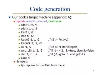
This project outlines a multi-view methodology for generating Verilog code for ASIP design environments, focusing on architecture, operation, simulator, and hardware views. It covers the design approach, composite actors, iterative SAT procedures, and hierarchical Verilog structure.

E N D
Verilog Code Generation for an ASIP Design Environment Nathan Kitchen Vinay Krishnan Mentor: Scott Weber (MESCAL) EE 244/249 Joint Project Fall 2002
Outline • Motivation • Design Environment • Approach • Example
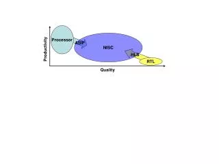
Motivation • Three ways to design a programmable system (ASIP): We are here
Bottom-up Instruction Set Design Traditional Top-down Design Bottom-up Design instruction set space ISA is fixed Any of these instruction sets can implement the application. architecture exploration micro-architecture space micro-architecture space
Teepee • Design environment for MESCAL • Multi-view methodology • Common data model for generating simulator, assembler, compiler, and netlist • Views are abstractions of the model • Can only use information present in the model • Not allowed to introduce new semantics • Architecture view: designer lays out datapath • Operation view: extracts operations from architecture • Simulator view: generates simulator program • Hardware view: generates synthesizable Verilog (our project)
Advantage of Multi-View Design data model simulation synthesis ≡? RTL C simulation synthesis RTL C gates gates silicon silicon Traditional: hard to verify equivalence of simulator and RTL written separately easier to verify correctness of transformations from common data model
sel in out Architecture View • Actors connected by signals between ports • Semantics of atomic actors defined by firing rules • Composite actors allow hierarchy or(fire(in[0].p.1.int32, in[1].p.0, sel.p.1.e, out.p.1.int32) {out = in[0];} fire(in[1].p.1.int32, in[0].p.0, sel.p.1.e, out.p.1.int32) {out = in[1];} no_fire(in[0].p.0, in[1].p.0, sel.p.0.e, out.p.0) {} )
inc in out sel sel in in out out dec in out Composing Actors Control ports (select lines) are left unconnected. Their values will be determined in the operation view.
Operation 1 Operation 2 Operation 3 Operation View Solve constraints on firing rules • Iterative SAT procedure • Only minimal solutions
Instruction Models Composite1 • Composite1 has separate instruction models for NOP, i_1, and i_2 • Composite2 has one instruction model for both i_1 and i_2 Composite2 i_1 i_2
Approach (cut to Vinay)
>> A Sample Architecture View
>> Fetch Unit
>> Program Counter
Verilog Structure • Preserve the hierarchical structure of the Architecture View • Atomic actors => Atomic modules • Composite actors => Composite modules
Atomic Modules • Actor semantics implemented with behavioral Verilog • Two parts: combinational logic and sequential state write • Procedural ‘always’ blocks implemented for both • Combinational logic in ‘always’ blocks instead of ‘assigns’ to avoid potential mux chains
Composite Modules • Act as containers for the modules inside them • Instantiate the inner modules • Route the wires appropriately • Merge control signals based on instruction models • Ground unconnected ports, if any
opcode parameter2 parameter1 Top-Level Module • Decodes instruction word • Converts opcodes to control signals which activate concerned atomic actors (one hot encoding of opcodes->control signals) • Multiple issue width achieved by multiple-hot encoding!
Tools • ModelSimPE 5.5ed • Synplicity Pro 7.1
Circuit Schematic architecture view
Fetch Unit architecture view
Program Counter architecture view
The Answer: 42
Prior Work • Architecture description languages • Behavioral ADLs • Describe instruction semantics • Lack information for synthesizing micro-architecture • Mixed ADLs • Describe semantics and micro-architecture • Tightly coupled with specific tools • Hardware description languages (e.g., Verilog) • Can describe any micro-architecture • No concept of operations
Future Work • Combine operations into more conventional instructions in assembler or compiler view • Multiple PEs