Download
1 / 57
570 likes | 593 Views
DreamBox is a digital music gadget combining practical functionality, entertainment system, and home decoration with dynamic and static modes. Features crystal bars, LED patterns, and beat detection algorithm.

E N D
Dream Box Mutrix Technology Benson Lam Shuozhi Yang Winfield Zhao Gary Heng Weiguang Mao
Agenda • Team Members and Roles • Design Motivation • Project Description and Features • System Overview • Schedule and Milestone • Final Thought • Team Dynamic
Team Members and Roles • Benson Lam – Chief Executive Officer (CEO) • Role in the project: • Benson Lam devoted most of his time in developing the firm software and designing the mechanical system of Dreambox. • Winfield Zhao – Chief Technical Officer (CTO) • Role in the project: • Winfield Zhao mainly focus on the whole mechanical system of Dreambox.
Team Members and Roles • Shuozhi Yang – Chief Programming Officer (CPO) • Role in the project: • Shuozhi is the main programmer in the team. His strong programming background is one of the key componets to the success of Dreambox. • Gary Heng – Chief Design Officer (CDO) • Role in the project • Gary focused on the design of amplitude patterns. He also built the beat algorithm.
Team Members and Roles • Weiguang Mou – Chief Financial Officer (CFO) • Role in the project: • Weiguang focused on the design of LED pattern. He also assisted building the mechanical system.
Design Motivation • Strong market for electronics devices • Digital music gadgets take a large portion • Digital picture frames • Digital music box • I-animals
Design Motivation • Durability won’t last long in the competitive market if: • Impractical functionality • lack of innovation • Solution: • A digital music gadget that has practical functionality • Entertainment system • Home decoration • DreamBox!!
Project Description and Features • Statue consists of 25 cells • Each cell has • Crystal bar • Mechanical system • LED
Project Description and Features • Two Modes of operation • Dynamic Mode: • A music player is connected to the system • Music is filtered and analyzed by an algorithm • Algorithm detect the beat level of the music and output different 3D shape • Static Mode: • Display shapes drawn by the users • The users first define shapes on the GUI • GUI communicate with the board and output the shapes users defined
Design and Implementation • Mechanical • Design Mechanical system • Component choosing • Hardware • Motor Controller • LED control circuit • dsPIC development board • ADC pre-processing circuit • Dynamic Mode • Beat Detection Algorithm • Static Mode • GUI • Communication • Pattern Design • LED pattern • Motor pattern
Design and Implementation- Mechanical System (1) • Main Components • Crystal Bar • Linear Movement Slot • Gear Rack and Gear Set • Servo Motor
Design and Implementation- Mechanical System (2) • Crystal Bar • Made of Thin Plastic Glass • Print with White • 4X4X9cm • Linear Movement Slot • Hold the Gear Rack in Place • Tricolor LED installed on the Top • Gear Rack and Gear Set • Translate Rotational Motion to Linear Motion
Design and Implementation -Mechanical System (3) • Micro Servo Motor • Allowable 180 degree turn • Control by Pulse Width from 0.5ms to 2.5 ms in 15 ms period • Operating Speed: 0.3sec/60degree
Design and Implementation- Hardware (1) • 4 Main Sections • Motor Controller • Tri-Color LED Control Circuit • dsPIC Development Board • ADC Pre-processing Circuit
Design and Implementation- Hardware (2) • Motor Controller – Lynxmotion SSC-32 Servo Controller • High Resolution 1us • Support up to 32 Servo Motors • Allow Single Move and Group Move • Serial Interface (RS-232)
Design and Implementation- Hardware (4) • Motor Controller – Data Formal • # <ch> P <pw> S <spd>... # <ch> P <pw> S <spd> T <time><cr> • <ch> =Channel number in decimal (0 – 31) • <pw> =Pulse width in microseconds (500 – 2500) • <spd> =Movement speed in uS per sec for one channel. (Optional) • <time> =Time in mS for the entire move, affects all channels, 65535 max. (Optional) • <cr> =Carriage return character
Design and Implementation- Hardware (5) • Tri-Color LED Control Circuit • Allow Full Color Control • Switching between each Color (Red, Blue and Green) • Allow Full Brightness Control
Design and Implementation- Hardware (6) • dsPIC Development Board – dsPICDEM GP 1.1 Plus Development Board • dsPIC30F6014A • 12-bit 200Ksps ADC • 4Kbytes EEPROM • Up to 30MIPS Operation • Two RS232 Channels • Four Push Buttons • 122X32 dot LCD • Audio Input & output Sockets
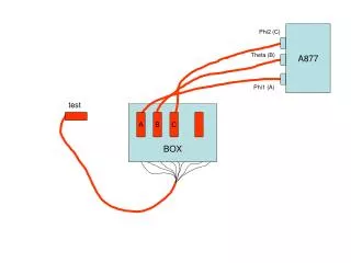
Design and Implementation-Hardware (7) • Pre-processing circuit for data capturing
Design and Implementation -Static Mode (1) • Display static decorative styles designed by users • Provide full control over all components of DreamBox • Provide users a convenient platform to design their own decorative styles
Design and Implementation -Static Mode (2) • Features • Ease of use: • Plug-and-play • Straightforward graphical user interface on PC • Simple user interface without PC • Recall user-designed styles at any time and any place • Full control over DreamBox • Crystal bars • LED’s
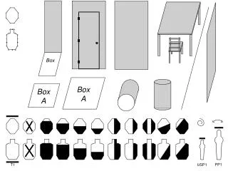
Design and Implementation-Static Mode (3) Static Display Mode
Design and Implementation-GUI (1) Establish Connection
Design and Implementation-GUI (2) Main Control Panel
Design and Implementation-GUI (3) Crystal Bar Mapping
Design and Implementation-GUI (4) LED Select Bar Rise (left-click) Bar Drop (right-click) Button Color Indication
Design and Implementation-GUI (6) Simple on-board GUI
Design and Implementation-Communication (1) • Establishing connection with DreamBox • Maintaining Connection • Saving Data to DreamBox
Design and Implementation-Communication (2) • Establishing connection with DreamBox • Handshake Stage I: GUI sends flag requesting for establishing connection; if no reply is received in timeout time, prompt message; if expected reply is receive, enter Handshake Stage II. • Handshake Stage II: GUI sends flag requesting data from DreamBox; if no reply is received in timeout time, prompt message; if data is received completely, GUI enters main control panel.
Design and Implementation-Communication (3) • Maintaining Connection • Step I: DreamBox sends confirmation byte to GUI if no command is received within certain amount of time • Step II: If no reply is received within timeout time, DreamBox exits from connection state; if expected reply is received, connection state is maintained
Design and Implementation-Communication (4) • Saving Data to DreamBox • Synchronized data transfer to provide sufficient time for EEPROM storing operation • DreamBox returns Rdy signal to GUI for each byte of data processed
Design and Implementation-Beat Detection Inspiration • Windows Media Player • Music Player – Winamp
Design and Implementation-Beat Detection Verification • Implemented beat detection algorithm in Matlab • Surprisingly accurate result
Design and Implementation-Analog to Digital Converter (ADC) • Sampling rate 46.1 KHz • Constantly interrupts the CPU for real time calculation
Design and Implementation-Beat Detection Algorithm • Compact Disc Quality • Design Choice
Design and Implementation-Pattern Design • Pre-defined Pattern Design • Welcome Pattern • Spiral Shape
Design and Implementation-Idle Mode • When Music is Unplugged or Paused • Static LED Sequence Displayed • 6 Random Assignment • Snake, Clock, Heart, Row Rotation, Diagonal Rotation, Disco
Design and Implementation-Low Beat State • Random Assignment
Design and Implementation-High Beat State • Random Assignment
Future Development • Increase Display Resolution • Wireless Connection • Noise Reduction • Signal Processing Algorithm Improvement
Funding Engineering Science Student Endowment Fund (ESSEF) Award $500 • School of Engineering Science $50