Download
1 / 23
240 likes | 474 Views
Capacitors: Review. A capacitor is a device that stores electrical potential energy by storing separated + and – charges 2 conductors separated by insulating medium + charge put on one conductor, equal amount of – charge put on the other conductor

E N D
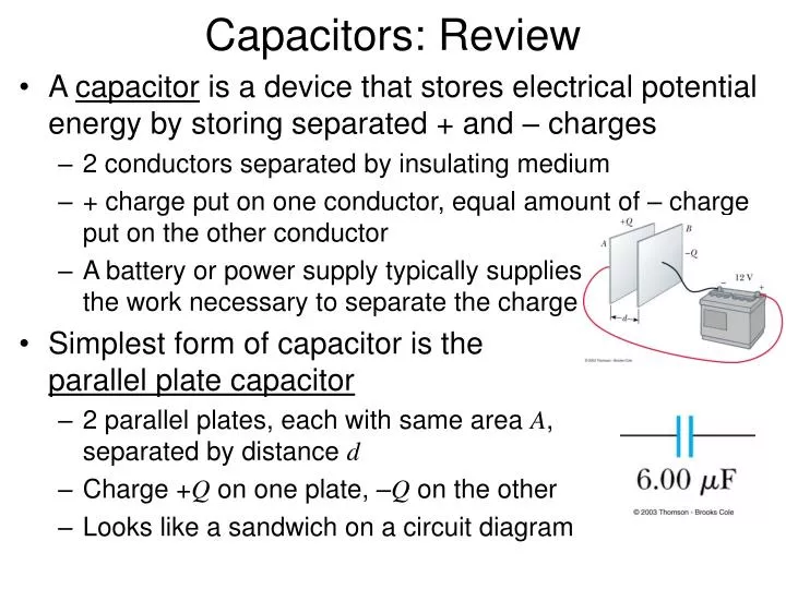
Capacitors: Review • A capacitor is a device that stores electrical potential energy by storing separated + and – charges • 2 conductors separated by insulating medium • + charge put on one conductor, equal amount of – charge put on the other conductor • A battery or power supply typically supplies the work necessary to separate the charge • Simplest form of capacitor is the parallel plate capacitor • 2 parallel plates, each with same area A, separated by distance d • Charge +Q on one plate, –Q on the other • Looks like a sandwich on a circuit diagram
Capacitors: Review • The charge Q onand voltage V across a capacitor are related through the capacitanceC • “Capacity” to hold charge for a given V • 1 F is very large unit: typical values of C are mF, nF, or pF • Capacitance depends on the geometry of the plates and the material (dielectric) between the plates • “Static” description of capacitors • A “dynamic” description of capacitor behavior comes from taking the time derivative of the above: • Current passed by a capacitor depends on rate of change of V Units: C / V = Farad (F)
Capacitors: Review • Water–pipe analogy of a capacitor • Capacitor can be regarded as an enlargement in a water pipe with a flexible membrane stretched across the enlargement (see figure below) • No water actually passes completely through pipe, but a surge of water flows out of the right–hand pipe • For capacitor, no DC current flows through, but AC current does • A stiff (flexible) membrane corresponds to small (large) capacitance (Introductory Electronics, Simpson, 2nd Ed.)
(Lab 2–1) RC Circuits: Review V • Consider a circuit with a resistor and an uncharged capacitor in series with a battery: • Voltage across capacitor increases with time according to: • A = –Visince V = 0 at t = 0 • Vi = maximum (battery) voltage (only reached at t = , but 99% of Vireached in t = 5t) Vi V 0.63Vi Vi Vi– V
(Lab 2–1) RC Circuits: Review V • Consider a circuit with a charged capacitor, a resistor, and a switch: • Before switch is closed, V = Vi and Q = Qi= CVi • After switch is closed, capacitor discharges and voltage across capacitor decreases exponentially with time: t = RC = time constant Vi 0.37Vi
(Lab 2–2) RC Circuits: Differentiators • Now consider the series RCcircuit as a voltage divider, with the output corresponding to the voltage across the resistor: • The voltage across C is Vin – V, so: • If RC is small, then and • Thus the output differentiates the input! • Simple rule of thumb: differentiator works well if (The Art of Electronics, Horowitz and Hill, 2nd Ed.)
RC Circuits: Differentiators (The Art of Electronics, Horowitz and Hill, 2nd Ed.) • Output waveform when driven by square pulse input: • What would happen if t = RC were too big? (See Fig. 1.38 in the textbook for an indication of what would happen)
(Lab 2–3) RC Circuits: Integrators • Now flip the order of the resistor and capacitor, with the output corresponding to the voltage across the capacitor: • The voltage across R is Vin – V, so: • If RC is large, then and • Thus the output integrates the input! • Simple rule of thumb: integrator works well if (The Art of Electronics, Horowitz and Hill, 2nd Ed.)
RC Circuits: Integrators (The Art of Electronics, Horowitz and Hill, 2nd Ed.) • Output waveform when driven by square pulse input: • What would happen if t = RC were too small? (See Fig. 1.33 in the textbook) (H&H)
Inductors: Review • Inductors act as current stabilizers • The larger the inductance in a circuit, the larger the opposition to the rate of change of the current • Remember that resistance is a measure of the opposition to current • The rate of current change in an inductor depends on the voltage applied across it • Putting a voltage across an inductor causes the current to rise as a ramp • Note the difference between inductors and capacitors • For capacitors, supplying a constant current causes the voltage to rise as a ramp • An inductor is typically a coil of wire (hence its appropriate circuit symbol)
The RLC Series Circuit: Review Series circuit consisting of a resistor, an inductor, and a capacitor connected to an AC generator • The instantaneous current in the circuit is the same at all points in the circuit • The net instantaneous voltage Dv supplied by the AC source equals the sum of the instantaneous voltages across the separate elements
The RLC Series Circuit: Review • But voltages measured with an AC voltmeter (Vrms) across each circuit element do not sum up to the measured source voltage • The voltages across each circuit element all have different phases (see figure at right) • We use the algebra of complexnumbers to keep track of the magnitude and phases of voltages and currents V(t) = Re(Vejwt) I(t) = Re(Iejwt) where w = 2pf V, Iare complex representations j = (–1)1/2 (see Appendix B) (Phase relations for RLC circuit)
Impedance • With these conventions for representing voltages and currents, Ohm’s law takes a simple form: V = IZ • V = complexrepresentation of voltage applied across a circuit = V0ejf • I = complex representation of circuit current = I0ejf • Z = total complex impedance (effective resistance) of the circuit • For a series circuit: Z1+ Z2 + Z3+ … • For a parallel circuit: 1 / Z = 1 / Z1+1 / Z2 + 1 / Z3+ … • The impedance of resistors, capacitors, and inductors are given by: • ZR= R(resistors) • ZC = XC = –j / wC = 1 / jwC (capacitors) • ZL = XL = jwL (inductors)
Complex Representation Example • The presence of the complex number j simply takes into account the phase of the current relative to the voltage • Example: place an inductor across the 110 V (rms) 60 Hz power line • The phase of the voltage is arbitrary, so let V = V0 V(t) = Re(Vejwt) V(t) = Re(Vcoswt + jVsinwt) = V0coswt • For an inductor, ZC = jwL • So the (complex) current is given by: I = V / Z = V0 / jwL = –V0j / wL • The actual current is then I(t) = Re(Iejwt) = Re(Icoswt + jIsinwt) = (V0/ wL)sinwt current lags the voltage by 90°
Phasor Diagrams • Can also use phasor diagrams to keep track of magnitude and phases of voltages • x axis represents the “real” part of the circuit impedance (resistance) • y axis represents the “imaginary” part of the circuit impedance (capacitive or inductive reactance) • Draw vectors to represent the impedances (with their signs); add the vectors to determine combined series impedance • Axes also represent (complex) voltages in a series circuit since the current is the same everywhere, so voltage is proportional to the impedance
Phasor Diagrams • = phase angle between input voltage and voltage across resistor or between input voltage and current • Example: series RC circuit • Total (input) voltage is obtained from a vector sum • Note that the vectors indicate phase as well as amplitude • Remember the mnemonic “ELI the ICE man” • In an inductive circuit (L), the voltage E leads the current I • In a capacitive circuit (C), the current I leads the voltage E f (Student Manual for The Art of Electronics, Hayes and Horowitz, 2nd Ed.)
AC Power • The instantaneous power delivered to any circuit element is given by P(t) = V(t)I(t) • Usually, however, it is much more useful to consider the average power: Pave = Re(VI*) = Re(V*I) • V and I are complex rms amplitudes • Example: hook up an inductor to a 1 V (rms) sinusoidal power supply • V = 1 • I = V / ZL= V / jwL = –jV / wL • Pave = Re(VI*) = Re(jV / wL) = 0 • Same result holds for a capacitor (this fun activity is free!) • All power delivered to an AC circuit is dissipated by the resistors in the circuit: • In general: where cosf = power factor
RC Circuits: High–Pass Filters (Lab 2–5) • Let’s interpret the differentiator RC circuit as a frequency-dependent voltage divider (“frequency domain”): • ZC = –j / wC = –j / 2pfC As f increases (decreases), ZCdecreases (increases) • Thus Vout (= voltage across R)increases with increasingf and Vout/ Vin 1 • Circuit passes high-frequency input voltage to output Resistor–only divider: RC differentiator circuit: C R1 R (Student Manual for The Art of Electronics, Hayes and Horowitz, 2nd Ed.) R2
RC Circuits: Low–Pass Filters (Lab 2–4) • Now simply switch the order of the resistor and capacitor in the series circuit (same order as the integrator circuit earlier): • ZC = –j / wC = –j / 2pfC As f increases (decreases), ZCdecreases (increases) • Thus Vout (= voltage across C)increases with decreasingf and Vout/ Vin 1 • Circuit passes low-frequency input voltage to output Resistor–only divider: RC integrator circuit: R R1 C (Student Manual for The Art of Electronics, Hayes and Horowitz, 2nd Ed.) R2
RC Filter Frequency Response • The point where the output “turns the corner” is called the 3dB point • Output is attenuated by 3dB relative to the input • Special because a signal reduced by 3dB delivers half its original power • A graph of Vout(or Vout / Vin) vs. f is called the frequency response of the RC filter: (for both types of filters) (Student Manual for The Art of Electronics, Hayes and Horowitz, 2nd Ed.)
R C Example Problem #1.25 Use a phasor diagram to obtain the low-pass filter response formula (Voutvs.Vin) on p. 37 of Horowitz and Hill. Solution details given in class.
Example Problem: Additional Exercise #1.3 Design a “rumble filter” for audio. It should pass frequencies greater than 20 Hz (set the –3dB point at 10 Hz). Assume zero source impedance (perfect voltage source) and 10k (minimum) load impedance (that’s important so that you can choose R and C such that the load doesn’t affect the filter operation significantly). Solution details given in class.