Download

1 / 120
1.25k likes | 1.51k Views
Transit Signal Priority Control Based On Cell Transmission Model. Using Reinforcement Learning. Ph.D. Viva Mr. Pitipong Chanloha 5071870721. Thesis Advisors Asst. Prof. Dr. Chaodit Aswakul Dr. Jatuporn Chinrungreung Asst. Prof. Dr. Wipawee Hattagam. WHAT & WHY BRT

E N D
Transit Signal Priority Control Based On Cell Transmission Model Using Reinforcement Learning Ph.D. Viva Mr. PitipongChanloha 5071870721 Thesis Advisors Asst. Prof. Dr. ChaoditAswakul Dr. JatupornChinrungreung Asst. Prof. Dr. WipaweeHattagam
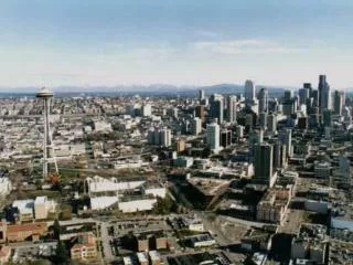
WHAT & WHY BRT (BUS RAPID TRANSIT) BTS High construction costs and long construction periods
WHAT & WHY BRT (BUS RAPID TRANSIT) MRT High construction costs and long construction periods.
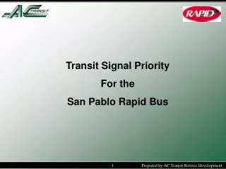
WHAT & WHY BRT (BUS RAPID TRANSIT) • Exclusive Lane
WHAT & WHY BRT (BUS RAPID TRANSIT) • Exclusive Lane • Signal Priority • Excellent Vehicle Design • Attractive Stations • Excellent Operations • Traveler information
BRT Issues Deduction of road network capacity Signal priority integration ONE DEDICATED LANE FOR BRT !!! TRANSIT SIGNAL PRIORITY !!!
BRT Issues TRANSIT SIGNAL PRIORITY !!! ONE DEDICATED LANE FOR BRT !!!
How to control the traffic signal priority? What about the other researchers?
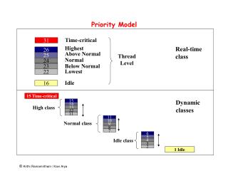
Traffic Models Mesoscopic Microscopic Traffic Signal Control Macroscopic Non-Priority Priority
Terminologies for the traffic models Microscopic model describesthe dynamic and stochastic modeling of individual vehicle movements within a system of transportation facilities – High computational power required. Macroscopic model usesthe conservation of flowand equations on how traffic disturbances propagate through the system like shockwaves – Low computational power required. Mesoscopiccombinesboth macroscopic and microscopicmodels. This model simulates individual vehicle (microscopic) but describes the vehicle interactions based on macroscopic relationships – Moderate computational power required.
How to control the traffic signal priority? What about the other researchers?
Literature Review Diagram [5] – SCOOT – Split Cycle Offset and Optimization Technique [7] – SCATS – Sydney Coordinate Adaptive Traffic [15] – Manual traffic signal control in different traffic behaviors.
Literature Review Diagram [26] – [28] – Adaptive Neuron Network (ANN) is used to predict the arrival patterns. [30] – [31] – Adaptive Dynamic programming is employed. The advance traffic information patterns are required. Consider in microscopic level.
Literature Review Diagram [25], [34] – Solve for traffic signal control for an isolated intersection. [33],[35] – Propose and use RL in the highway. [36] – [40] – Signal optimisation becomes a major concern but the traffic characteristics are not incorporated. Consider in microscopic level.
Literature Review Diagram [43] – First proposed a signalised CTM version. [44] – Apply CTM and optimise the traffic signal with TRANSYT (determine the optimal fixed time with a set of fixed traffic volume). [45] – CTM signal is optimised by mixed-integer linear programming.
Literature Review Diagram – Active priority – Needs the intelligence of the system to adapt and response to the traffic signal control. [11],[12],[14] – SCOOT with transit signal priority. [18] – [19] – Control the traffic signal priority to reduce delay and enhance the travel time estimation. [20] – [21] – Try to reduce the bus headway and local information to control the traffic signal light. [22] – [24] – Centralised control. It requires enormous amount of computation and cost of installation
Literature Review Diagram – Passive priority – Fixed time strategy. It can be weighted and reoptimised. [16] – Grants the green extension or recall to a bus. [17] – Similar to [13], two extra conditions have been considered. Limit green time extension and minimum elapsed time after the priority period.
Literature Review Diagram – [29] – Genetic Algorithm is employed to seek for optimal traffic signal plan. ANN is used to predict the traffic patterns. Consider in a microscopic level.
How to start? END OF CHAPTER 2
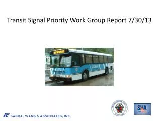
BRT Route in Bangkok,Thailand An isolated system
Motivated Road Network Cell Transmission Model (CTM)
Mathematical Formulation State Space Definition
Mathematical Formulation State Quantisation
Mathematical Formulation Cell Transmission Model (CTM) Sending Capability I I+1
Mathematical Formulation Cell Transmission Model (CTM) Receiving Capability I I+1
Mathematical Formulation Cell Transmission Model (CTM) Cell Cascading I-1 I
Mathematical Formulation Cell Transmission Model (CTM) Flow Conservation
Mathematical Formulation Cell Transmission Model (CTM) Action–phase of signal to be chosen
Mathematical Formulation CTM – Boundary Conditions Sink Cell Cell Buffered (Gate Cell) Source Generator Desired link input flow
Mathematical Formulation Cell Transmission Model (CTM) Vehicle delay
Mathematical Formulation Cell Transmission Model (CTM) Performance Criteria
Mathematical Formulation What we have done so far? • State space • CTM structures • Sending capability • Receiving capability • Cell cascading • Flow conservation • Action space • Traffic signal light • Boundary conditions • Vehicle delay • Performance criteria
How to find the most proper traffic signal control for an isolated intersection? Signal Optimisation By Reinforcement Learning
Traffic network patterns cannot be predicted. • RL can be adjusted to find the solution upon the change of traffic patterns. • RL does not need offline learning period to process the enormous amount of data. Why reinforcement learning?
State Action Reward(Penalty) Agent Signal Optimisation by Reinforcement Learning Environment Learning a mapping from the environment to actions in order to maximise (minimise) a reward function/value.
State Action Reward(Penalty) Agent Signal Optimisation by Reinforcement Learning Environment
State Action Reward(Penalty) • State space /Quantised state space • Action definition • Reward function • Vehicle delay Agent The requirementof RL (Q-learning) Environment
Define • Simulation time • Time length used to study the traffic behaviourse.g. 4 hours. • Episode :time interval granularity to represent recurrent/non-recurrent traffic conditions • e.g. 20 minutes (2400 time slots). Optimisation Procedure
For each episode, • System Initialisation • Action Selection • Measurement and Update of System Dynamics • Update of Action-Value Function • Update Parameter • Stopping Condition Optimisation Procedure
Step : 1/6 • System initialisation • Initialise number of vehicles in the road. • Initialise action-value function (the average future reward returned.) • Initialise CTM parameters. • Initialise RL state by observing # of vehicles in the system. Optimisation Procedure
Step : 2/6 • Action Selection • Choose an action to control traffic signal • The action has been selected byε-greedy algorithm • The probability is given to the greedy action • The probability is given to each of non-greedy actions • The greedy action is defined as Optimisation Procedure
Step : 3/6 • Measurement and Update of System Dynamics • After taking action, an immediate reward R(ω) has to be observed • Q-learning updates every decision epoch tω • Decision epoch refers to the time instant where an event ω occurs. Moreover, the decision must be made when event ω occurs. Optimisation Procedure
Step : 4/6 • Update of Action Value Function • To evaluate how good the action selection is Optimisation Procedure The increment to be added to the previous estimated Q-value. Action value function for next state
Step : 5/6 • Update parameters • Update state • Update next decision epoch Optimisation Procedure • Step : 6/6 • Stopping condition • Repeat steps 2-5 until the end of simulation time
Results Series of investigations • Validation, computational complexity • Effects of reward functions • Q-learning with its adaptability in stationary/non-stationary traffics • Applicability range in microscopic traffic simulator AIMSUN Under review: ASCE Journal of Transportation Engineering CHAPTER 3
Results Series of investigations • Road of 800metres long. It is divided into 10 CTM cells. • Cell capacity 60 passenger car units (pcu). • Maximum flow rate is 6.9 pcu/slot • Wave speed coefficient is 0.8 • Arrival process : deterministic • Simulation time = 240 time slots. • 1 time slot = 5 seconds. • Quantisation level = 3. Under review: ASCE Journal of Transportation Engineering CHAPTER 3