Download
1 / 30
300 likes | 431 Views
U. Goerlach, L ECC Colmar Sept 2002. Front-End Hybrids for the CMS Silicon Tracker. Design Considerations and a some History Technology Choices First Prototypes on Ceramics and Results New Developments in Rigid-Flex and Full-Flex Technology

E N D
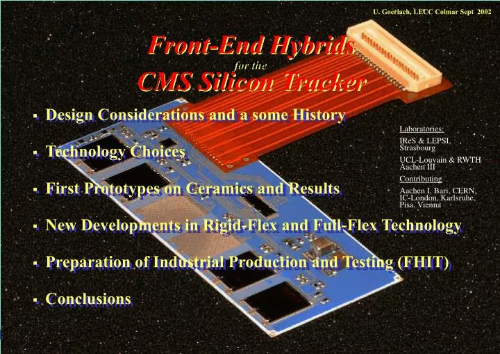
U. Goerlach, LECC Colmar Sept 2002 Front-End Hybrids for the CMS Silicon Tracker • Design Considerations and a some History • Technology Choices • First Prototypes on Ceramics and Results • New Developments in Rigid-Flex and Full-Flex Technology • Preparation of Industrial Production and Testing (FHIT) • Conclusions Laboratories: IReS & LEPSI, Strasbourg UCL-Louvain & RWTH Aachen III Contributing Aachen I, Bari, CERN, IC-London, Karlsruhe, Pisa, Vienna
Design Considerations and some History • Start in 2000 • Definition of functionality • Modularity: hybrid geometries and shapes • Technology choices • Option for fully industrial production • 2000-2002 • Prototyping in thick-film technology ca. 180 FE-hybrids • Many design changes to adapt to detector-module integration • Electrical system tests • Development of an automatic test-station (FHIT) for industrial production • Identification of industrial partners • 2002 • Revision of initial technology choice • Start of industrial production planned N.Marinelli, Tuesday: Hybridsneed some additional work
60 mm APV Detector bias return 47 mm 25+3 mm 25+3 mm NAIS 40 pin MUX PLL DCU SAMTEC 20 pin NAIS 30 pin Definition of FE Hybrid (I) • Electrical functionality (2002): • Analogue read-out chips 4 or 6 APV25 • Power lines, grounding, decoupling • Auxiliary chips: MUX, PLL and DCU • Measurements (with DCU-chip) of : • Supply voltages, • Temperatures on hybrid and detector (with internal and external thermistors) • Detector bias return current • No HV on hybrid • Connector(s) to interconnect-cards and opto-hybrid for analogue read-out
Definition of FE Hybrid • Multi-layer board • Mechanical parameters • Two geometries • Heat transport to frame ( 3 Watt) • Support of pitch-adapter • Thickness limitations, less than one mm without components • No connector on the hybrid • Rigid and flat within 100 mm • Operation at -10° to -20 °C • Radiation hardness • Electrical parameters (2002) • 4 metal layers • Via: Ø 100/300 mm • Line width: 120 mm • Separations (line/via): 180/90 mm • Bias line resistance: 20-50 mW • Kapton cable • 1 or 2 connectors (NAIS and SAMTEC) • Bending radius of 1-1.5 mm (180° turn) • SMD components • Minimal height • R and C of type 0402 and 0603 • LPCC (since 2002): MUX, PLL, DCU • Naked die ASICs to bond • 4 or 6 APVs, alignment 30 mm • (MUX-PLL) • (DCU) • Glob-top cover for bonds? (Radiation hardness ?)
Modularity and Geometries TOB TEC TOB TEC TID TIB (Version 2002) TIB TID Need industrial production!
InterConnect Cards Patch panel InterConnect Bus 110 cm 15 cm Cooling pipe Module frame TOB-rod Opto-hybrids
Loaded TOB Rod with Si-Detector Modules Used for double sided modules
Technology choices (I) Technology Candidates • Industrial availability and price • Xo budget of tracker • Radiation safety (no Ag) (Very approximate figures!)
Technology choices (II) • Thermo-mechanical properties • Heat (max. 3 Watt) has to be transported to detector frame • CTE compatibility with module frame material: • Hybrid will be glued on frame (carbon fibre or graphite) • Deformation • Lift-off • Many simulations and tests to validate concept and substrate-material • Suitable for automatic mounting on Gantry • Flatness • Rigidity • Integration of cable and connector(s) ?
47 mm 28 mm DCU Kapton cable Optohybrid Interconnect card Prototyping in Thick-Film Technology on Ceramic Substrates (2000-2001) • First Circuits produced at CERN Workshop then • Populated with SMD and ASICs and then • Tested in Strasbourg • • APVs need careful bias decoupling on V125 • Market survey MS2991 (Spring 2000) • Small via diameters and spacing at industrial technical limit (120 mm) • Very few candidates Combined MUX-PLL chip (naked die) Small pitch: Min.: 115 mm MUX_PLL
V250 4.7-10 mF V125 4.7-10 mF VSS V250 V250 V250 V250 V250 V250 100 nF 100 nF 100 nF 100 nF 100 nF 100 nF Common bias lines V125 V125 V125 V125 V125 V125 100 nF 100 nF 100 nF 100 nF 100 nF 100 nF VSS VSS VSS VSS VSS VSS Read-Out Chip (APV) Stability on Hybrid Decoupling of APV-power rails: VSS Oscillation on V125 power line (across 4.7 mF) ca. 80 kHz, 200 mV Power line resistances on hybrid from connector to APV: 20-40 mW, including 15 mW in cable M.Raymond, IC London
Solution to APV (In-)Stability M.Raymond, IC London • Split V125 line for preamplifier and inverter • Re-generate V125 from V250 by individual 100 W resistor • Solution has been tested up to common resistances of up to 5 W on the V125 line • Robust solution • New split power pads (bonding!):
Dorazil and MIPOT Ceramic Hybrids After a market survey (MS2991) only two companies agreed to produce hybrids for CMS Tracker M200 Milestone at reasonable price 150 hybrids 5 hybrids • Main Difficulties: • Small feature size not suitable for mass production • Soldering of kapton cable • Main Difficulty: • At technical limit of company
Noise: < > » 300 e- APV 1+2 pedestals APV 3+4 calibration APV 5+6 Uniformity: Merging all APVs calibrations APV Read-Out on Hybrid • Good APV performance preserved on FE-hybrid!
Irradiation Test of Ceramic FE-Hybrid Frank Hartmann IEKP - Universität Karlsruhe (TH) • Proton current: 2 µA " 26 MeV protons " • Irradiation of 120x120mm2 up to 1014 p/ cm2 takes 20 min • Irradiation of Hybrid • During irradiation: • Clock, • Trigger (10Hz), • Error Buffer Readout (1Hz), • Reset • Irradiation with 2 µA protons up to 2.7 1014 p/ cm² (~ 30years LHC) • First verification at cyclotron with over 5m cables and provisional readout ( Hybrid is still activated (2µSv) ) • Hybrid still alive! • Irradiation of some SMD components and glue has been performed by the Vienna group • All final components have to be qualified with irradiation!
Summary on Ceramic Hybrids • In total about 180 ceramic hybrids were produced • Yield about 80% (we did not repair everything) • About half will be used for prototype Si-detector modules until December • Assembly procedure • Performance in test beam • Different electronic and electrical and mechanical system tests for the configurations of TIB TOB and TEC. • Temperature cycles • Irradiation tests • General concept of FE-hybrid validated • Several changes requested ( re-design of layout) • Re-design with larger feature size necessary • Possible with new encapsulated control chips in 0.5mm pitch housings • Now other potentially significant cheaper technologies available • New R&D and industry survey necessary at very late stage of project
New Technological Choices Prototyping I • With new LPCC Control and Service ASICS • MUX, PLL, DCU • Multi-layer board in “advanced” FR4 printed circuit board technology • Could be very cheap in large quantities • First circuits in January 2002 • Boards are correct • Great difficulties to solder cable Only a few working proto-types • Next step was cable integration: • Rigid-Flex hybrid FR4 board with connector
Polyimide FR4-Noflow FR4 copper Coverlay Thickness New Technological Choices Prototyping II • Flex-Rigid(FR4) Hybrid: • Different companies with slightly different technologies and quality • 2 bottom layers on rigid FR4 • 2 upper layers on polyimide • Tolerances in thickness up to 100 micron • Non-Flatness in the order of 100 micron before SMD montage, and we have seen more • Extend FR4 part under PA • More prototype boards available soon Promising path, but quite a bit more expensive than a simple FR4 board
CICOREL Polyimide 25 micron Lamination 25 micron Copper 20 micron New Technological Choices Prototyping III • Flex-Flex (all Kapton) laminated on • Carbon-fibre substrate • FR4-substrate with thermal heat conducts • Mechanical properties • Final rigidity? • Final flatness < 100 mm? • Proto-types available soon Carbon fibre or FR4 Coverlay 25 Pi + 25 glue
Industrial Production of FE-Hybrids • Large quantities (more than 15000) can only be produced reliably in industry • Numbers will help to achieve uniformity throughout production • Industry will also be charged with the final acceptance test before delivery • Preferably only one manufacturer or consortium, delivering final product • Technical specifications have to be well defined before tendering • Careful evaluation and system tests mandatory! • Qualification of manufacturer by proto-type runs • Quality assurance during production: • In depth test/characterisation of random samples • Some temperature or other cycles in industry before final acceptance test • Relay on industrial standard during mass production • Duration of production will be about one year N.M.: Final results of system test expected in spring 2003
Front-End Hybrid Industrial Tester (I) • Task: Simple acceptance test of hybrid in factory • Components: • Mechanical structure • Transition board (FEHC) • FHIT: electronic circuit including switching matrices Active component, a connection to ARC and fast Controllers • ARC Read-out system • Power supplies • PC • Barcode reader • Software ARC board
Front-End Hybrid Industrial Tester (II) Test sequence: Power supply control • Barcode scanning, recognition of hybrid type • Continuity test • Electrical test, including I2C scan • Functionality test (read-out of APVs) • Log file creation + error file + hybrid identification file XML (CMS database) Response (simplified for operator!): greenor red light Block diagram http://www.fynu.ucl.ac.be/themes/he/cms/activities/tracker/hybrids.html
I_125 I_250 APV current consumption distribution
DCU ADC calibration Signal amplitude as a function of MUX resistors being switched on
Summary and Conclusions • Successful development of FE-hybrids for the CMS-tracker • In total we have produced over 200 hybrids in different technologies • Proto-typing of FE-hybrids in thick film on ceramic • Required performance achieved! • Many modifications implemented to help system integration! • Need for revised layout using ASICs with larger footprint • Now open to new (cheaper) technologies • New technologies (FR4, flex-rigid, full-flex) are being explored • Proto-types in industry in progress • Will determine final technical specification and the choice of substrate • Full industrial production foreseen (duration is about one year) • Industrial tester has been developed for acceptance test • Quality assurance: • Relies on large scale industrial production standards • Extensive characterisation of samples during production
DCU INL < 1LSB • Digital Test: OK • -1 LSB < DNL < 1 LSB • Transient noise RMS ~ 1/4 LSB • Power dissipation < 40mW • ADC Gain vs. X-ray dose: -0.4 %/Mrad • No evident changes in INL and transient noise RMS during and after X-ray irradiation Gain ~ 2.2 LSB/mV
Study of frames deformations and cooling efficiency RWTH Aachen I grid CCD reflecting surface >100mm dummy hybrid at correct temp.