Download
1 / 65
650 likes | 850 Views
Addressing Power Issues within an Integrated RTL-to-GDSII Flow Fusion 2003. Patrick Groeneveld Magma Design Automation,. Agenda. Introduction Tight integration through Magma data model Using the tool: TCL and GUI interface Gate sizing technology for silicon integrity

E N D
Addressing Power Issues within an Integrated RTL-to-GDSII FlowFusion 2003 Patrick Groeneveld Magma Design Automation,
Agenda • Introduction • Tight integration through Magma data model • Using the tool: • TCL and GUI interface • Gate sizing technology for silicon integrity • Power & voltage drop analysis with Blast Rail
Silicon Virtual Prototyping Routing closure Battling wire congestion Crosstalk noise & delay Timing closure IR voltage drop, Electromigration Battling parasitic capacitances Engineering an RTL to GDSII flow Timing closure (parasitic cap.) BIST insertion Routing closure Clock gating Hierarchy, Partitioning, design planning Design scale, concurrent design Flip-chip packaging Block/macro placement Block/macro placement Testability Load buffering synthesis Mapping for speed ECO capability Noise buffering Diode insertion Clock skew Decoupling caps, package design Multi-VDD regions Low power requirements Large capacity and fast algorithms Timing/sizing driven placement IR voltage drop, Electromigration Gate sizing (gain based synthesis) Delay buffering place High I/O count design flow Parasitic extraction & estimation Cloning, logic restructuring IR-drop and Power analysis Congestion control Antenna rules Useful skew clock synthesis Spare cell insertion DSM mask rules DRC/ERC Balanced clock trees Antenna-friendly routing, jumper insertion Crosstalk noise & delay Timing analysis Power infrastructure Dual-hierarchy support Hold time violations Scan chain reordering and routing Rip-up and reroute Yield, reliability, PVT Correct-by-construction tools route Clock shielding Etc. etc. etc. Wire spacing Wire spacing Wire widening Dual Vt support Filling, slotting, router adaptations Wire shielding Hold time buffering
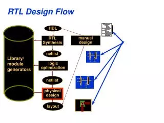
Timing Constraints RTL LIB Design Compiler Jupiter/Planet Floor plan PLIB PDEF Net List lef2plib Apollo II Liberty model LEF GDS II (lib) gds2lef GDS II StarRC PrimeTime SPEF Compare: ‘Bolting’ a flow together using files • The real value is in the flow, not in the algorithms • Yet, design data is spread over many files • Files are big and slow to read. • Redundant information is stored: • less memory efficient. • Relevant information gets lost in the translation • interpretation may not be consistent • DSM issues are everywhere, the file interface makes dealing with them harder. PrimeTime Net List Physical Compiler
Power planning Rail EM/Signal EM Power consumption P&R Crosstalk glitch Voltage drop Crosstalk delay Voltage-drop- Induced delay Timing Addressing Signal and Power Integrity • Signal and power integrity pose major concerns for today’s DSM designs • Problem is compounded as timing, SI, and power are all inter-related • Solutions available today rely on multiple point tools • Involves file transfers and data translation - leads to potential errors • Too many iterations between analysis and implementation tools • Lack of predictability may cause problems to be discovered too late – high cost of fixing Designers spend too much time converging to a solution
Tool integration through a database e.g. placer e.g. GUI e.g. timer Tool 1 Tool 2 Tool 3 Tool 4 Tool 189 Tool 190 internal datastructure internal datastructure internal datastructure internal datastructure internal datastructure internal datastructure api api api api api api common data base with all data. • The database interfaces with the tools through and API or files. • Each tool makes its own copy (data structure) of the data. • It takes memory and time to haul all this data around
Timing Alg. External formats or tools Verification Alg. Placement Alg. TCL access Routing Alg. ... GUI access Tool n Alg. Volcano on disk The data model is key • Use a simple (data) model that can be used by multiple algorithms without elaborate translations • Many interdependent problems will have to be intertwined into a flow. • Consistency of interpretation is key in-core Data Model
Tight & efficient tool integration Routing Mask layout RTL Placement CDFG Net list of Super Cells
Victim net Aggressors spaced out Victim net Aggressors attacking Supporting cross talk fixing • Post-route Silicon repair flow: • parasitic extraction • run timer • Determine/filter problem (e.g. crosstalk noise) • re-route victim: • redo-global route • redo-detailed route • And/or resize and buffer: • insert & place gate • redo-global route • redo-detailed route • parasitic extraction • run timer • etc. etc. etc. • Traditionally: Export gds2, generate SPEF, run delay calc, run timing, fix design
Magma Data model supports incremental design and analysis • You can add, change or delete • any object • at any time • Such changes are tracked by the data model, it keeps itself consistent at any time. • The incremental analysis tools detect such change automatically • … and update of only the affected parts • The timer, extractor and DRC engine are brutally incremental • They do not require to be started explicitly. • Result: fast and simple operation.
library.volcano rtl.volcano logic.volcano floorplan.volcano place.volcano route.volcano final.volcano ‘Volcanoes’: snapshots of the flow • The contents of the magma data structure can be written to disk at any time during the design flow. A volcano contains a complete snapshot of all design data. • Resume operation, or use as backup. Timing constraints Designrules (.lef gds2) Floorplan (.def) .lib RTL Verilog/ vhdl Magma flow GDSII mask data 600Mb 30Mb
Interfacing with the data model through TCL • Complete access: • inspect, modify or delete any object or attribute • TCL scripts also drive the flow • Also the Graphical User Interface interfaces through TCL • easy configuration and adaptation
check model $m -level final run route stub $m run route global $m -antenna run route track $m -optimize noise run route power $m -final check route spacing_short $m check route open -segment $m run route final $m -singlepass run route antenna $m run route refine $m run route final -incremental $m check route drc $m Magma RTL-to-GDS flow outline in TCL (batch) set m [import verilog mydesign.v] import volcano library.volcano fix rtl $m $l fix time $m $l fix plan $m $l fix cell $m $l fix clock $m $l fix wire $m $l export volcano mydesign.volcano export gdsii $m mydesign.gds
Lets start the tool • Accounts are called magma1, magma2, through magma15. • Just log in and have fun. • In unix shell, type ‘mantle’
Timing is poorly predictable • Gate-to-gate delay depends on: • Driver gate size. • Wire length (unknown during logic synthesis) • The configuration of the neighboring wires: • distance, near/far (unknown before detailed routing) • The layer of the wire (determined during routing) • Timing window and slope of the neighboring wires.
Creal Conventional layout synthesis size + parasitics = timing s Cdream slack slack
Result: many iterations logic synthesis PARASITICS (estimate) => gate SIZE place & route gate SIZE + PARASITICS = TIMING
Creal Gain-based physical synthesis: timing + parasitics = size s Cdream slack
What happens when gates are sized? Load moves 'upstream' when delay is kept 1x 2x out out Both inverters have approx. the same delay. Notice that the input capacitance increased 2x vdd vdd vdd vss vss vss in in
Key: simple model for step B Cin Cload “Fast circuit design on a napkin” Ivan Sutherland (1991): Delay = (g * h) + p Fixed part, parasitic delay Delay of the gate + its load Logical effort depends on function of gate Electrical effort proportional to output load Cload / Cin For details: See the book: ‘Logical Effort’ by Sutherland, Sproull, Harris Morgan Kaufmann publishers, ISBN 1-55860-557-6
Logical effort: g • To keep the same output drive strength, the 2 n-transistors in series must double their size. • As a result, the input capacitance of the nand is larger. • For the same output drive strength, an inverter needs less input capacitance. • More complex gates have less gain same drive strength Nand 2: Cin = 4/3 Inverter: Cin = 1
Logical effort: g • Assuming that in static CMOS gates the mobility of the p-transistor is half of the n-mobility: • 3-input nor
Gain-based synthesis: supercells • We extract the super cells from the library description (.lib, lef) • Contains: • g, h, p • size-range Super!
Aggressive gate sizing • The gain ratio (=Cload/Cin) is maintained is placement • Sizes change during placement. • As a result, delay is kept (almost) constant. Cload/Cin = fixed
Pre-layout timing check 0.5ns 0.5ns 0.5ns 0.5ns ff ff ff ff FF You must change RTL! • If there is no feasible gain assignment, the sizes literally ‘explode’. • ESP: gain is a measure of the ‘tightness’ of the constraints
Load violations • Maximum drive strength in the library might be too small • Drive information is stored in super cell, and managed pre-placement. • Buffering, cloning and restructuring are used to maintain delay during placement Cin 4x 2x 1x Cload Permissible range Load violation
Keeping delay fixed 0.6ns 0.6ns 0.6ns 0.6ns FF • Actively managing wire delay: • Through automatic sizing (sizing-driven placement) • Through buffer insertion • Cloning
Recap: What happened • Cell Area fixed • Delay is a gamble • Worst case delay determines timing (max) • Iterate to make ends meet. • Only critical paths are addressed. Therefore gates will be too big: • waste of area • waste of power • Cause unnecessary agressors …. at the logical-physical boundary? • Delay fixed • Cell Area unknown • Sum of areas determines chip size • No iterations required • benefit: speed • All cells are sized, so each gate has exactly the right drive strength: • Not too little • Not too much (waste of area) • Avoids SI problems Mamga Gain based synthesis Conventional synthesis
Integrated Signal & Power Integrity Solution • Concurrently addresses crosstalk, power, voltage drop, electromigration, OCV, and timing problems • Correct-by-construction methodology eliminates iterations and reduces design cycle time • Patented unified data model architecture enables on-the-fly correction • Unified Implementation flow – single executable
Power & Voltage Drop Analysis Throughout The Flow • Enables analysis early and often to ensure predictability • Power analysis – static and dynamic • Accounts for leakage, switching, and short-circuit (crowbar) power • Easy, flexible setup from .lib • Switching activity can be specified or read in (VCD, GAF or SAIF) • Activity propagation • Voltage drop analysis - dynamic and transient • Dynamic looks at switching activities over multiple clock cycles • Transient analysis accounts for voltage glitches within a cycle • Uses network parasitics - decoupling caps, package inductances • Addresses timing changes due to voltage drops • Performs cell-based derating • Calculates timing changes without going to external STA • Concurrent optimization makes necessary design changes
Concurrent Optimization For Timing, Power & SI • Unique FixedTiming methodology is the key • Defers sizing decisions until later stage • Sizes drivers optimally to match actual load • Slew balancing minimizes victim/aggressor pairs • Analyze-Avoid-Adjust methodology ensures signal integrity • Advanced analysis models identify potential problems • Optimization engines make on-the-fly changes to address them • Power management throughout the flow • Reduces power & area by ideal sizing • Additional techniques used to reduce static and dynamic power 30% power reduction 13% area reduction Better timing Faster TAT
Blast Rail power analysis steps in magma flow Library data RTL synthesis Floor planning net list Power infrastructure generation (rails, mesh) VCD file Activity annotation & propagation floor plan with or without placed gates Slews from the built-in timer/extractor Power Analysis Rail network extraction Power consumption report Current & voltage drop calculation Voltage & current sources, resistances What-if?? Voltage drop induced delay Voltage drop and EM textual reports Physical synthesis and optimization flow GUI
cp1 Ry/2 L cp2 cp4 Rx/2 Rx/2 A metal wire in a routing layer is modeled by a rectangle, called a segment, that has up to four connection points and four resistances: Ry/2 cp3 W Rx = Rsheet W/L Ry = Rsheet L/W Rail Network Description Rail Extraction The network combines • Physical description of the power grid • Electrical description of the power grid
Network Features Rail Extraction Electrical nodes • Node number • Layer • List of segments • Voltage (user-specified, extracted, calculated) Segments • Rectangular shape • Layer * • Resistance (or more) * • Up to four nodes • List of pins (cell pins and model pins)
Blast Rail power analysis steps in magma flow Library data RTL synthesis Floor planning net list Power infrastructure generation (rails, mesh) VCD file Activity annotation & propagation floor plan with or without placed gates Slews from the built-in timer/extractor Power Analysis Rail network extraction Power consumption report Current & voltage drop calculation Voltage & current sources, resistances What-if?? Voltage drop induced delay Voltage drop and EM textual reports Physical synthesis and optimization flow GUI
Defining Switching Activity Activity annotation • The switching activity of a signal describes the following characteristics: • The probability that the signal is logic one • The rising toggle rate • The falling toggle rate • By default, the tool is looking at the switching activity over a one second time interval.
Ways to define Switching Activity Activity annotation • Option 1: Specify switching activity using: force activity annotate • Example: Basic clock running at 150MHz and non-clock nets at 10% of clock force activity annotate $m -probability 0.2 -toggle 15e6 data loop net model_net $m { if { [query net is_clock $net] } { force activity annotate $net -probability 0.5 -toggle 300e6 } }
Ways to define Switching Activity Activity annotation • Option 2: Import VCD (value change dump) format data from logic simulation using: import vcd • Option 3: Let tool set switching activity based on clock defined for static timing analysis • The clock nets are switching twice (rise/fall) per cycle • The non-clock nets are set to 50% of maximum clock frequency found from input cone • Nets without clock phase information are set to 0 unless default activity is defined • Example: config activity default 1e6
Propagating switching activity Activity annotation • Option 4: Propagate switching activity using: force activity propagate • Propagates switching activity from primary inputs and sequential element outputs • Logic function of gate is used to obtain switching activity at the gate outputs {0.2,10} {0.8,10} {0.842,8.48} {0.7,5} {0.21,2.9} Notation: { probability, toggle rate } {0.3,2}
Blast Rail power analysis steps in magma flow Library data RTL synthesis Floor planning net list Power infrastructure generation (rails, mesh) VCD file Activity annotation & propagation floor plan with or without placed gates Slews from the built-in timer/extractor Power Analysis Rail network extraction Power consumption report Current & voltage drop calculation Voltage & current sources, resistances What-if?? Voltage drop induced delay Voltage drop and EM textual reports Physical synthesis and optimization flow GUI
Vdd Vdd Vin Vout Vin Vout Cload Cload Gnd Gnd Gnd Gnd What influences current? • event/state • slope • load • PVT Power Analysis - CMOS dissipation
D Q CL Power calculation Given cell with pins: • State = stable state of pin-values • Event = change of (any) pin-value • State related dissipation • leakage • bias currents (typ. zero for CMOS) • Event related dissipation • dynamic (cap. loading) • short circuit • Where do we get it from? • .lib, CV2
Blast Rail power analysis steps in magma flow Library data RTL synthesis Floor planning net list Power infrastructure generation (rails, mesh) VCD file Activity annotation & propagation floor plan with or without placed gates Slews from the built-in timer/extractor Power Analysis Rail network extraction Power consumption report Current & voltage drop calculation Voltage & current sources, resistances What-if?? Voltage drop induced delay Voltage drop and EM textual reports Physical synthesis and optimization flow GUI
Viewing the Voltage Drop Report ###################################################################### # Mantle analysis report # Command: # report rail analysis vdrop \ # /work/incrementer/incrementer/net:VDD –max_nodes 4 # Date: Fri Oct 4 01:40:10 2002 # Version: mantle.linux version 3.2.a.50-linux22_x86 # IR-Drop Analysis Configuration: # IR-drop iteration mode: off # Automatic power pad pin detection is turned on. ###################################################################### IR-drop on net: /work/design/design/net:VDD (2.300 V). Node x (um) y (um) layer voltage drop ------ -------- -------- ------ ------------ 70 19.020 45.760 metal1 783.1 uV 81 26.940 45.760 metal2 783.1 uV 132 17.820 45.760 metal2 782.8 uV 67 11.055 45.760 metal1 782.0 uV
Viewing Results in the GUI GUI Open the Power/Rail Analyzer form from the Layout window Tools -> Power/Rail Analyzer
Current Map GUI