Novel Offset Mirror System for Background Reduction in LCLS Beam Experiments
This proposal outlines a system utilizing total-reflection mirrors to mitigate significant unwanted background radiation in the LCLS beam, primarily caused by spontaneous harmonics and Bremsstrahlung. The system features pairs of SiC and Be mirrors positioned to deflect FEL radiation while collimating apertures eliminate non-reflected background. Reflectivity studies indicate high efficiency for energies below 24 keV for SiC mirrors. Essential technical considerations include creating a new white beam optics enclosure and ensuring alignment of high-quality mirrors to avoid damage from intense FEL pulses. Discussions on shielding and facility adjustments are ongoing.


Novel Offset Mirror System for Background Reduction in LCLS Beam Experiments
E N D
Presentation Transcript
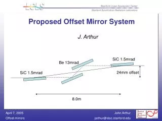
Proposed Offset Mirror System J. Arthur SiC 1.5mrad Be 13mrad 24mm offset SiC 1.5mrad 8.0m
The Problem Unfiltered LCLS beam contains significant background from spontaneous harmonics (Ec ~ 150 keV) and from Bremsstrahlung from scattered electrons (GeV) Much of this background lies directly on axis, and it is time-coincident with the FEL pulse This is a nuisance for radiological shielding, and a huge problem for data taking
The Proposed Solution Use total-reflection mirrors to deflect FEL radiation (and 3rd harmonic, up to 24 keV). Use collimating apertures to eliminate non-reflected background
Reflectivity vs energy for a flat SiC mirror at 1.5 mrad incidence angle R > 95% for E < 24 keV R < 10% for E > 28 keV From Berkeley CXRO calculator: <http://www.cxro.lbl.gov/optical_constants/mirror2.html>
The mirror system will consist of two mirror pairs. One pair will be inserted at a time. The SiC pair gives a cutoff at 24 keV; the Be pair gives a cutoff at 2 keV. Interlocks can be used, if necessary, to assure that one of the mirror pairs is always inserted. SiC 1.5mrad Be 13mrad SiC 1.5mrad 24mm offset 8.0m
Technical Issues Create new White Beam Optics Enclosure by moving shielding in FEE upstream 5mm apertures define FEL beam (plus core spontaneous) Alignment is critical Need high-quality mirrors Risk of damage to mirrors from intense FEL pulse
Proposed layout of FEE 4 ft Fe 3 ft concrete 4 ft Fe SiC MIR Be MIR GAS ATTEN STOP ADJ SLIT COLLIM ADJ SLIT STOP SOLID ATTEN 15m 11.6m >2M SPACE FOR DIAGS ~0.6M SPACE FOR DIAGS
4 ft Fe 3 ft Concrete 4 ft Fe 3 ft Concrete 24mm offset 1m 0.65m 8.0m 3.78m 9.0m 1m 2.13m 11.65m 2.13m Pop-in camera location
Status of Proposal Radiation Physics has examined shielding implications, presented preliminary report Discussion between XTOD and XES regarding real estate in FEE, commissioning plan, etc. Conventional Facilities implications are understood Final decision expected soon