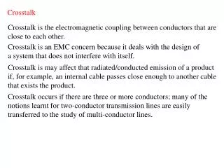
Download
1 / 15
150 likes | 312 Views
An Interconnect BIST for Crosstalk Faults based on a Ring LFSR. T. Garbolino, K. Gucwa, A. Hławiczka , M. Kopeć Institute of Electronics Silesian University of Technology, Gliwice, Poland. EWDTS’09, September 18-21, 2009, Moscow, Russia. Outline.

E N D
An Interconnect BIST for Crosstalk Faults based on a Ring LFSR T. Garbolino, K. Gucwa, A. Hławiczka, M. Kopeć Institute of Electronics Silesian University of Technology, Gliwice, Poland EWDTS’09, September 18-21, 2009, Moscow, Russia
Outline • Crosstalk faults in long interconnects in SoCs • Two test patterns for detection of crosstalk faults • Classical Ring LFSR • Shift dependency – fault stimulation problem • Fault masking due to mutual cancellation phenomenon • Proposed solution - 3n-RT-LFSR • Experimental results • Conclusion
La Aggressor (A) La Aggressor (A) Lv Victim (V) Lv Victim (V) 0 La Aggressor (A) La Aggressor (A) Lv Victim (V) Lv Victim (V) 1 Crosstalk faults (a single aggressor) Positive glitch Falling edge delay Negative glitch Rising edge delay
La1 Aggressor (A) La2 Aggressor (A) Lv Victim (V) La3 Aggressor (A) La1 Aggressor (A) La1 Aggressor (A) La2 Aggressor (A) La2 Aggressor (A) Lv Victim (V) Lv Victim (V) 1 La3 Aggressor (A) La3 Aggressor (A) Crosstalk faults(multiple aggressors) Positive glitch Falling edge delay La1 Aggressor (A) La2 Aggressor (A) Lv Victim (V) 0 La3 Aggressor (A) Negative glitch Rising edge delay
Two-test patterns Positive glitch Negative glitch
Two-test patterns Falling edge delay Rising edge delay
Mutual cancellation phenomenon • D-MISR – high fault masking due to mutual cancellation of error sequences • T-MISR – much more resistive to mutual cancellation phenomenon Hławiczka A., Gucwa K., Garbolino T., Kopeć M.: „Can a D flip-flop based MISR compactor reliably detect interconnect faults?” Proc. DDECS 2005, pp. 2-8.
Experimental results n– bus width (#interconnections) k - #aggressors L -#test patterns g – test sequence length t – computation time
k=3 k=4 Experimental results L - #test patterns g – test sequence length
Conclusion • Effective BIST structure for testing of crosstalk faults in interconnects • Solution is independent on topology of interconnect network under test • 100% of required two-test patterns are generated for k << n • More resistive to mutual cancellation phenomenon • Acceptable test sequence length • 3n-bit signature – high diagnostic resolution • Computation time needed for finding solution is reasonable • The most probable static faults are also detected