Download
1 / 1
10 likes | 171 Views
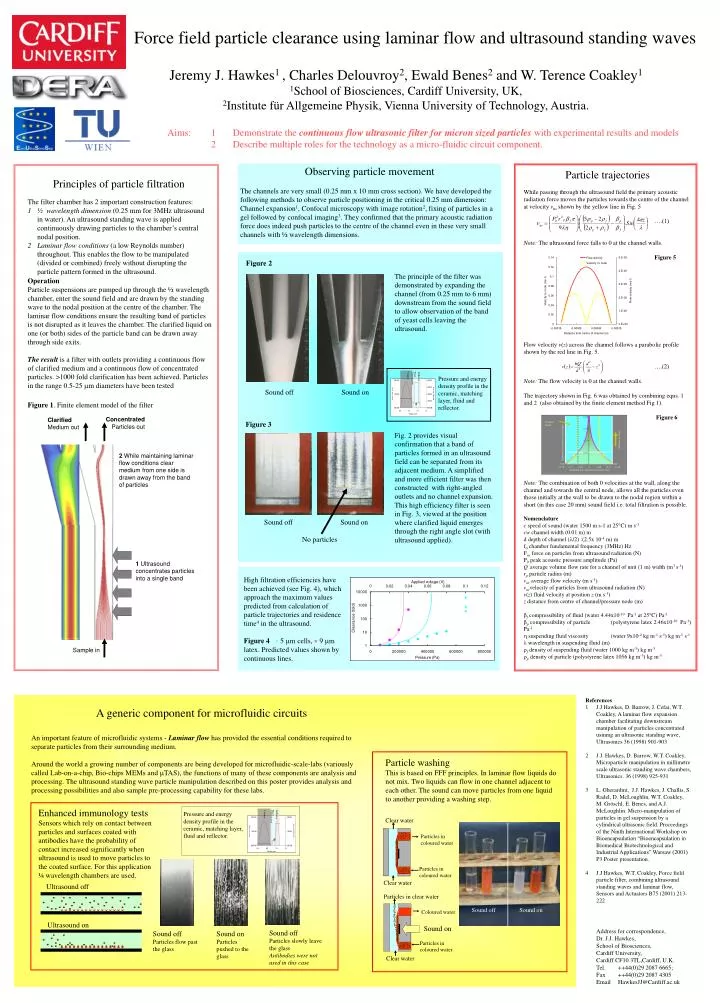
Water. Transmission. Ceramic. Reflector. 0.08. Clarified liquid. 0.06. Ceramic. Water. Transmission. Reflector. Direction of flow. Distance from start of sound field (m)…. 0.04. Sound off. Sound on. 0.02. 0. -0.15. -0.1. -0.05. 0. 0.05. 0.1. 0.15.

E N D
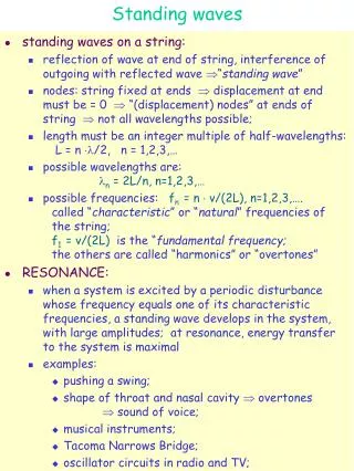
Water Transmission Ceramic Reflector 0.08 Clarified liquid 0.06 Ceramic Water Transmission Reflector Direction of flow Distance from start of sound field (m)…... 0.04 Sound off Sound on 0.02 0 -0.15 -0.1 -0.05 0 0.05 0.1 0.15 Distance from centre of channel (mm) Clear water Particles in coloured water Particles in coloured water Ultrasound off Clear water Particles in clear water Ultrasound on Coloured water Sound on Sound off Particles slowly leave the glass Antibodies were not used in this case Sound off Particles flow past the glass Sound on Particles pushed to the glass Particles in coloured water Clear water Force field particle clearance using laminar flow and ultrasound standing waves Jeremy J. Hawkes1 , Charles Delouvroy2, Ewald Benes2 and W. Terence Coakley1 1School of Biosciences, Cardiff University, UK, 2Institute für Allgemeine Physik, Vienna University of Technology, Austria. Aims: 1 Demonstrate the continuous flow ultrasonic filter for micron sized particles with experimental results and models 2 Describe multiple roles for the technology as a micro-fluidic circuit component. Observing particle movement The channels are very small (0.25 mm x 10 mm cross section). We have developed the following methods to observe particle positioning in the critical 0.25 mm dimension: Channel expansion1, Confocal microscopy with image rotation2, fixing of particles in a gel followed by confocal imaging3. They confirmed that the primary acoustic radiation force does indeed push particles to the centre of the channel even in these very small channels with ½ wavelength dimensions. Particle trajectories While passing through the ultrasound field the primary acoustic radiation force moves the particles towards the centre of the channel at velocity vus shown by the yellow line in Fig. 5 ….(1) Note: The ultrasound force falls to 0 at the channel walls. Figure 5 Flow velocity v(z) across the channel follows a parabolic profile shown by the red line in Fig. 5. ….(2) Note: The flow velocity is 0 at the channel walls. The trajectory shown in Fig. 6 was obtained by combining eqns. 1 and 2 (also obtained by the finite element method Fig 1). Figure 6 Note: The combination of both 0 velocities at the wall, along the channel and towards the central node, allows all the particles even those initially at the wall to be drawn to the nodal region within a short (in this case 20 mm) sound field i.e. total filtration is possible. Nomenclature c speed of sound (water 1500 m s-1 at 25C) m s-1 cw channel width (0.01 m) m d depth of channel (/2) :(2.5x 10⁻⁴ m) m f0 chamber fundamental frequency (3MHz) Hz Fus force on particles from ultrasound radiation (N) P0 peak acoustic pressure amplitude (Pa) Q ‘average volume flow rate for a channel of unit (1 m) width (m3 s-1) rp particle radius (m) vav average flow velocity (m s-1) vusvelocity of particles from ultrasound radiation (N) v(z) fluid velocity at position z (m s-1) z distance from centre of channel/pressure node (m) fcompressibility of fluid (water 4.44x10⁻¹⁰ Pa-1 at 25C) Pa-1 p compressibility of particle (polystyrene latex 2.46x10⁻¹⁰ Pa-1) Pa-1 : suspending fluid viscosity (water 9x10⁻⁴ kg m-1 s-1) kg m-1 s-1 wavelength in suspending fluid (m) f density of suspending fluid (water 1000 kg m-3) kg m-3 p density of particle (polystyrene latex 1056 kg m-3) kg m-3 • Principles of particle filtration • The filter chamber has 2 important construction features: • ½ wavelength dimension (0.25 mm for 3MHz ultrasound in water). An ultrasound standing wave is applied continuously drawing particles to the chamber’s central nodal position. • Laminar flow conditions (a low Reynolds number) throughout. This enables the flow to be manipulated (divided or combined) freely without disrupting the particle pattern formed in the ultrasound. Figure 2 The principle of the filter was demonstrated by expanding the channel (from 0.25 mm to 6 mm) downstream from the sound field to allow observation of the band of yeast cells leaving the ultrasound. Operation Particle suspensions are pumped up through the ½ wavelength chamber, enter the sound field and are drawn by the standing wave to the nodal position at the centre of the chamber. The laminar flow conditions ensure the resulting band of particles is not disrupted as it leaves the chamber. The clarified liquid on one (or both) sides of the particle band can be drawn away through side exits. The result is a filter with outlets providing a continuous flow of clarified medium and a continuous flow of concentrated particles. >1000 fold clarification has been achieved. Particles in the range 0.5-25 mm diameters have been tested Pressure and energy density profile in the ceramic, matching layer, fluid and reflector. Sound off Sound on Figure 1. Finite element model of the filter Concentrated Particles out Clarified Medium out Figure 3 Fig. 2 provides visual confirmation that a band of particles formed in an ultrasound field can be separated from its adjacent medium. A simplified and more efficient filter was then constructed with right-angled outlets and no channel expansion. This high efficiency filter is seen in Fig. 3, viewed at the position where clarified liquid emerges through the right angle slot (with ultrasound applied). 2 While maintaining laminar flow conditions clear medium from one side is drawn away from the band of particles Sound off Sound on No particles 1 Ultrasound concentrates particles into a single band High filtration efficiencies have been achieved (see Fig. 4), which approach the maximum values predicted from calculation of particle trajectories and residence time4 in the ultrasound. Figure 4 5 m cells, 9 m latex. Predicted values shown by continuous lines. Sample in • References • 1 J.J Hawkes, D. Barrow, J. Cefai, W.T. Coakley, A laminar flow expansion chamber facilitating downstream manipulation of particles concentrated usinmg an ultrasonic standing wave, Ultrasonics 36 (1998) 901-903 • 2 J.J. Hawkes, D. Barrow, W.T. Coakley, Microparticle manipulation in millimetre scale ultrasonic standing wave chambers, Ultrasonics. 36 (1998) 925-931 • 3 L. Gherardini, J.J. Hawkes, J. Challis, S. Radel, D. McLoughlin, W.T. Coakley, M. Gröschl, E. Benes, and A.J. McLoughlin. Micro-manipulation of particles in gel suspension by a cylindrical ultrasonic field. Proceedings of the Ninth International Workshop on Bioencapsulation “Bioencapsulation in Biomedical Biotechnological and Industrial Applications” Warsaw (2001) P3 Poster presentation. • 4 J.J Hawkes, W.T. Coakley, Force field particle filter, combining ultrasound standing waves and laminar flow, Sensors and Actuators B75 (2001) 213-222 A generic component for microfluidic circuits An important feature of microfluidic systems - Laminar flow has provided the essential conditions required to separate particles from their surrounding medium. Around the world a growing number of components are being developed for microfluidic-scale-labs (variously called Lab-on-a-chip, Bio-chips MEMs and TAS), the functions of many of these components are analysis and processing. The ultrasound standing wave particle manipulation described on this poster provides analysis and processing possibilities and also sample pre-processing capability for these labs. Particle washing This is based on FFF principles. In laminar flow liquids do not mix. Two liquids can flow in one channel adjacent to each other. The sound can move particles from one liquid to another providing a washing step. Enhanced immunology tests Sensors which rely on contact between particles and surfaces coated with antibodies have the probability of contact increased significantly when ultrasound is used to move particles to the coated surface. For this application ¼ wavelength chambers are used. Pressure and energy density profile in the ceramic, matching layer, fluid and reflector. Address for correspondence, Dr. J.J. Hawkes, School of Biosciences, Cardiff University, Cardiff CF10 3TL,Cardiff, U.K. Tel. ++44(0)29 2087 6665; Fax ++44(0)29 2087 4305 Email HawkesJJ@Cardiff.ac.uk