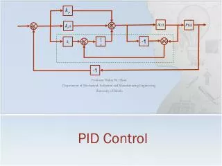
DirectLOGIC PID
DirectLOGIC PID. Setup and troubleshooting of a PID loop. BEGIN SETUP. TROUBLE- SHOOTING. Initial Setup …. The following steps will guide you through the initial steps for setting up a PID loop in the PLC. For best results, connect to your CPU and have it in Program mode. Select P LC

DirectLOGIC PID
E N D
Presentation Transcript
DirectLOGICPID • Setup and troubleshooting of a PID loop. BEGIN SETUP TROUBLE- SHOOTING
InitialSetup… • The following steps will guide you through the initial steps for setting up a PID loop in the PLC. • For best results, connect to your CPU and have it in Program mode. • Select PLC • Select Setup • Select PID
… initial setup • You should now see the ‘Set PID Table Address’ window. • Set the ‘Table Start Address’. Allow yourself 32 words for each complete PID table. • See table below for valid V-Memory ranges. • Assign the total ‘Number of Loops’. This will vary according to the CPU you are using. • See table below for max loops per CPU. • Once these are assigned you should select ‘Update and Exit’. V-Memory Ranges Max Loops Per CPU
Minimum Requirements … • These next steps will walk you through the setup for items that are ‘required’ for a basic loop to operate. • We will cover the ‘Setup PID’ window, tab by tab. • ‘Doc’ tab is optional. • ‘Configure’ tab: see ‘Details’ for more in-depth information on each. • Algorithm: select the following • Position • Sample rate: 0.05 (sec.) • Forward acting • Transfer Mode: • Bumpless I or II is OK • SP / PV & Output format: • Common format • Common Data Format: • Unipolar data format • 12-bit data format • Loop Mode: • Unselected Configure Details
Basic Setup … SP/PV • Basic setup requires nothing to be changed in this tab. • ‘SP/PV’ tab: see ‘Details’ for more in-depth information on each. • Setpoint Variable: No changes required for the loop to work • Address: Is fixed and determined by the beginning Loop table address • Remote SP: Only used w/ Cascading Loops • Enable Limiting: This is optional • Process Variable: No changes required for the loop to work • Address: Is fixed and determined by the beginning Loop table address • Sq. root: Not selected. Used only in certain specific apps. • Auto transfer: Not selected. (good option) see ‘Details’ for more information • SP/PV Data Format: • Only selectable if ‘Independent format’ • was selected in the Configure tab. SP/PV Details
Basic Setup … Output • Basic setup does require changes in this tab. • ‘Output’ tab: see ‘Details’ for more in-depth information on each. • Output: Upper limit must be set • Address: Is fixed and determined by the beginning Loop table address • Upper Limit: Can vary, but should typically be set to match the maximum range value • Lower Limit: Can vary, but should typically be set to match the minimum range value • Auto transfer: Not selected. (good option) see ‘Details’ for more information • Output Data Format: • Only selectable if ‘Independent format’ • was selected in the Configure tab. Output Details
Basic Setup … Tuning • Basic setup requires nothing to be changed in this tab. (Values are required, but can be set later in the PID view) • ‘Tuning’ tab: see ‘Details’ for more in-depth information on each. • At least one of these variables must be set in order for the loop to calculate an output. • It is possible to run with only one set and there are specific applications that work better with only specific P-I-D values active. • A very high percentage of all processes that we see, will work well with only P-I values active. • Gain/Bias: Values can be set now or later. You can also Autotune from the PID window and let the process calculate the values. • Gain (Proportional): Will vary per process. This is a multiplier for the error. • Reset (Integral): Will vary per process. This is a time constant that determines the frequency that the error is added to the bias. • Freeze Bias: Selected. (good option) • see ‘Details’ for more information • Rate (Derivative): Will vary per process. This • is a compensation that reacts to sudden change. • Derivative gain limiting: Not selected. • Error: No selection required. • Error Squared: Specific applications only. • Enable Deadband: Specific applications only. Tuning Details
Basic Setup … Alarms • Basic setup requires nothing to be changed in this tab. • ‘Alarms’ tab: see ‘Details’ for more in-depth information on each. • The alarms are monitor function ONLY. They have no bearing on the loop functions, unless you act upon them in the ladder. • Limit Alarms: No values required • High-High: Maximum or critical High alarm. • High: Minimum or non-critical High alarm. • Low: Minimum or non-critical Low alarm. • Low-Low: Maximum or critical Low alarm. • Monitor Rate of Change: No values required • Enable PV Deviation: No values required • Alarm hysteresis: No value required Alarm Details
Basic Setup … R/S • Basic setup requires nothing to be changed in this tab. • ‘R/S’ tab: Ramp / Soak will be covered in a separate trainer. Please consult your manual for detailed information about the setup and implementation of the Ramp / Soak table. • Table Location: Determined by the user. Completely separate from the PID loop table address. • Ramp/Soak Enable: Not selected. Enables the setup of the ramp / Soak table. • Ramp: Acceleration to a specific setpoint. • SP: Target Setpoint • Slope: The time it will take to achieve the target SP. • Soak: Hold time. • Time: The duration it remains at the target SP. • Deviation: Error, set by you, that triggers if the PV • varies from the SP by more than this amount.
Basic Setup … Complete • Once you have been through all of the tabs, you are ready to save your configuration. • The Icons on the Setup PID window allow you to write you current configuration to the PLC and to your disk. You also have the options to read from PLC or disk if you want to load an existing configuration into a new loop. • As mentioned before, the ‘Doc’ tab allows you to place a description w/ your process. This is useful if there is more than one loop in your application. • You are now ready to run your PID loop.
Starting the PID ... • You will now want to switch the CPU to ‘RUN’ mode. • It is not necessary to have any ladder code at this point. The CPU does require an END statement before it will switch to RUN. We will discussed data transfer with ladder logic later in the trainer. • It is recommended that you open the ‘PID view’ and ‘Data View’ windows.
Viewing the PID ... • This is one option. • By viewing both windows, you can • compare your variables in the PID View with • the actual values in the V-memory location in • a Data View window. • Make sure you reference page 8-8 of • the USER manual for details on what each • word of the PID loop table represents.
System in Operation … • With this view, you can see where the • P-I-D values have been set and the process is • controlling. • In the data view window, you can see • the current SP, PV& Output values, along with • the rest of the PID table addresses. • Make sure you reference page 8-8 of • the USER manual for details on what each • word of the PID loop table represents. P I D
Ladder Code ... • In the Ladder you want to make sure that the • SP and PV are in BIN data format before they are • moved to the PID table address. • Then verify that the Output from the PID is • converted from BIN to BCD as needed. • Make sure you reference page 8-8 of the • USER manual for details on what each word of the • PID loop table represents. This table is also a good • reference for the data type of each word.
… Configure Details • Select from the following data sheets for specific details on the area you are looking for. Transfer Modes: Algorithm: Position -vs- Velocity Forward -vs- Reverse BMP I -vs- BMP II Sample Rate Loop Mode: SP/PV & Output Format: Unipolar -vs- Bipolar 12-bit 15-bit 16-bit Common -vs- Independ. Independ. of CPU Configure Tab SP/PV Details Output Details Tuning Details Alarms Details
… SP/PV Details • Select from the following data sheets for specific details on the area you are looking for. Set Point: Process Variable: Address Remote SP Pointer Enable Limiting Address Square root Auto Transfer SP/PV Format: Unipolar -vs- Bipolar 12-bit 15-bit 16-bit Common -vs- Independ. SP/PV Tab Configure Details Output Details Tuning Details Alarms Details
… Output Details • Select from the following data sheets for specific details on the area you are looking for. Output: Address Auto Transfer Limits Output Format: Unipolar -vs- Bipolar 12-bit 15-bit 16-bit Common -vs- Independ. Output Tab Configure Details SP/PV Details Tuning Details Alarms Details
… Tuning Details • Select from the following data sheets for specific details on the area you are looking for. Gains & Bias: -P- Proportional Gain -I- Integral Gain -D- Derivative Gain Bias Limits & Errors: Freeze Bias Derivative Gain Limiting Error Sq. Enable Deadband Tuning Tab Configure Details SP/PV Details Output Details Alarms Details
… Alarm Details • Select from the following data sheets for specific details on the area you are looking for. Rate of Change: Limit Alarms: Limit Alarms Monitor Rate of Change PV Deviation: Alarm Hysteresis: Enable PV Deviation Alarm Hysteresis Alarms Tab Configure Details SP/PV Details Output Details Tuning Details
Algorithm : • Position -vs- Velocity Profile • A high percentage of all applications are Position. • This will include your standard heating and cooling • loops and most position or level controls. • A typical Velocity control would consist of a • process variable like a flow totalizer. As the definition • explains, it is working off of a “rate of change.”
Sample Rate: • Typically you will find that a faster sample rate • will give you better results in your process. One of the • only reasons for extending your sample time is if your • PID process is not that critical and your CPU scan is a • higher priority.
Forward/Reverse Acting: • You will find that everyone defines this part of the control differently. One systems Forward (direct) acting may be completely opposite from another. So it is very important to read this section to determine how you intend on your process to react. • Forward or Direct acting is also known as a heating loop. The greater the error (SP-PV), the greater the output will be. • If you manually increase the output, the PV will increase. (forward) • Reverse acting is, of course, right the opposite. • The greater the error the less the output. • If you manually increase the output, the PV will • decrease. (reverse)
Bumpless Transfer Modes: • This is intended to keep your system from slamming the • output in one direction upon initial startup. If a system has • been off and the error (SP-PV) is great, it can cause your • output to jump full on or full off, in turn shocking the system • or damaging the output device. This is designed to keep • that from happening. • The different modes allow you to select how much • suppression you want to place on your process. • Note: Bumpless Transfer I will always set the SP equal to the • PV on a Manual to Auto mode change. If you do not want this • feature, select Bumpless Transfer II.
Common -vs- independent: • This allows you to configure the PID more closely with your actual process. You may have a 16-bit resolution input module while your output module is only 12-bit resolution. • By selecting Independent Format, you can set the SP/PV separately from the Output. This selection grays out the format selection in the Configure Tab and enables the selection in the SP/PV tab as well as the Output Tab • The Common Format will allow you to select one format for the entire process, SP/PV & Output. This selections grays out the format selection in the SP/PV tab as well as the Output Tab and enables the selection in the Configure Tab.
Unipolar -vs- Bipolar: • Unipolar and Bipolar selection is pretty straight forward. • Unpolar is values above zero. (ex. 0 to 4095) • Bipolar is positive & negative values. (ex. -4095 to +4095)
12-15-16-Bit Resolution: • The resolution you select will be determined by the • modules that are supplying the SP/PV and the module • receiving the Control Output or the data value range that • your process needs to control. • Most of our Analog modules are 12-bit resolution. • The exception would be the THM & RTD temperature • modules and isolated output modules which are 16-bit.
Common -vs- independent: • This allows you to configure the PID more closely with your actual process. You may have a 16-bit resolution input module while your output module is only 12-bit resolution. • By selecting Independent Format, you can set the SP/PV separately from the Output. This selections grays out the format selection in the Configure. Tab and enables the selection in the SP/PV tab as well as the Output Tab • The Common Format will allow you to select one format for the entire process, SP/PV & Output. This selections grays out the format selection in the SP/PV tab as well as the Output Tab and enables the selection in the Configure Tab.
Unipolar -vs- Bipolar: • Unipolar and Bipolar selection is pretty straight forward. • Unpolar is values above zero. (ex. 0 to 4095) • Bipolar is positive & negative values. (ex. -2047 to +2047)
12-15-16-Bit Resolution: • The resolution you select will be determined by the • modules that are supplying the SP/PV and the module • receiving the Control Output or the data value range that • your process needs to control. • Most of our Analog modules are 12-bit resolution. • The exception would be the THM & RTD temperature • modules and isolated output modules which are 16-bit.
Limit Alarms: • The limit alarms give you a good way to monitor your system. If the process gets out of control, you can have the PLC let you know. You can have a visual alarm in the PID view as well as using the PID mode word to trigger bits and react upon those in the ladder.
Monitor Rate of Change: • This calculation works off of the amount that the • PV has changed in one sample time period. You set the • ‘maximum’ rate of change you would expect in your • process and if it exceeds this value you will get an alarm • notification.
PV Deviation: • The PV deviation alarms are a good way • to monitor a stable process. With this you can • determine if the process is going out of control.
Alarm Hysteresis: • This works in conjunction with other • alarm settings to give you a way to omit • nuisance alarms generated by erratic fluctuations • in the process.
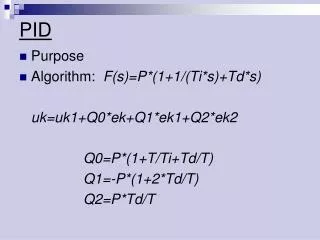
Proportional Gain: • The Proportional Gain is the most widely used factor of • the three values in the algorithm. It is basically a multiplier. • Take the error (SP-PV) and multiply it times the ‘P’ value and • that is your output.
Integral Gain: • The Integral Gain is calculated by the error (SP-PV). The • value of time in this setting determines how often the current • error is added to the Bias.
Derivative Gain: • The Derivative Gain is the least likely to be used of all the • gains. This is basically a compensator. It compares the current • error (SP-PV) with the previous error and adjust accordingly. • The majority of all processes we find can be controlled • with a P-I loop to required standards.
Freeze Bias: • Freeze Bias is an excellent option in processes that are slow to • respond. In slower applications, the the Output will climb to the max • value before the Process Variable reaches the Set Point. During this • time the Bias term will continue to increment. Once the PV crosses • the SP, the Bias must ‘unwind’ before the output will start to drop.
Bias: • The Bias term, like the Control Output, is a calculated value that • is determined by the algorithm. The Bias begins with the initial Output • value and builds from there. On each Manual to Auto transition, you will • see the Bias is set equal to the current output. The result of the integral • term is then added to the Bias.
Derivative Gain Limiting: • Because the Derivative Gain’s main purpose is to compensate • for a drastic change in the process, this makes it vulnerable to signal • noise in the PV. This limit allows you to place a ‘clamp’ on the • Derivative gain so the process does not get out of control.
Error Squared: • You will find that this is typically not used. It has specific applications • where it comes into play and that is only when you will see it used.
Error Deadband: • The Error Deadband is an area that is equally above and below the • Set point. While the PV is within this area the error is equal to 0. • Once beyond this area the error assumes it’s current value.
Output Address: • The Output address is determined by the starting PID loop • table address. The address is V+05. (V = starting loop address) • value is fixed and can not be changed. • Refer to the Loop Table Word Definitions chart on page • 8-8 of your USER manual.
Output Limits: • These limits are important in the PID function. The upper limit is mandatory • before an actual output will be generated. If there is an output upper limit of zero, • as soon as the PID algorithm begins to calculate it thinks it has reached its max • limit and shuts off. • The values are not read on-the-fly. Meaning that if you try to write to these • location it will not acknowledge the data until the next PLC mode change.
Auto Transfer to Output module: • Simple and easy to setup. Just select the slot of the CPU base the analog output • module is in and select the channel on the card that this loop will be controlling. • This is a very nice feature but should only be used if you do not plan • on using any of the channels of the analog card for any other reason except • for PID outputs. • This, like any other setup method for the analog card, • is telling the CPU how to write data to the module. If this is • selected in conjunction with another programming method • it will cause conflicts in the CPU memory. • Note: This option is not available in the D4-450 CPU
Set Point Address: • The Set Point address is determined by the starting PID loop • table address. The address is V+02. (V = starting loop address) • value is fixed and can not be changed. • Refer to the Loop Table Word Definitions chart on page • 8-8 of your USER manual.
Process Variable Address: • The Process Variable address is determined by the starting PID • loop table address. The address is V+03. (V = starting loop address) • value is fixed and can not be changed. • Refer to the Loop Table Word Definitions chart on page • 8-8 of your USER manual.
Remote SP Address Pointer: • The Remote SP address pointer is determined by the starting PID • loop table address. The address is V+32. (V = starting loop address) • This is ONLY used in Cascade loop mode. If this address is setup • for normal loop operation, you could experience trouble with this or an • adjacent loop not going into Auto mode. • In the Minor loop setup, the Remote SP Address Pointer is set to the • Control Output (V+05) of the Major Loop. • Refer to the Loop Table Word Definitions chart on page • 8-8 of your USER manual.