Download
1 / 13
130 likes | 304 Views
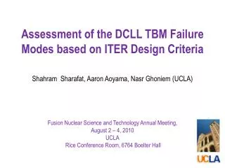
Development of a robust Be/F82H diffusion bond for ITER TBM. R.M. Hunt Fusion Nuclear Science & Technology Annual Meeting August 2, 2010. Introduction. Application : Development of TBM technologies vital for future fusion demonstration reactors Breeder blanket structural material

E N D
Development of a robust Be/F82H diffusion bond for ITER TBM R.M. Hunt Fusion Nuclear Science & Technology Annual Meeting August 2, 2010
Introduction • Application: Development of TBM technologies vital for future fusion demonstration reactors • Breeder blanket structural material • Reduced activation ferritic/martensitic (RAFM) steel • Plasma facing armor material • Beryllium is one primary candidate • Prospective Joining Process: Hot Isostatic Pressing (HIP) • Scope of Research: • Create methodology for development of a robust diffusion bond between beryllium and RAFM steel • Characterize the strength of the developed bond • Simulate cyclic thermal loading in FEM to determine min. strength criteria • Plastic relaxation of interface from differential thermal expansion • Crack initiation and growth at interface edges Armor coating on plasma facing surfaces
Background Important bonding considerations: • Formation of brittle intermetallic layers • Be is highly reactive w/ most of the elements in the periodic table • These often have much less desirable mechanical properties than parent materials • Formation is not easily predictable • Bond strength appears to be inversely proportional to width of certain reaction layers [1] • Excessive heat treatment of the bonded materials • Beryllium shows grain coarsening above roughly 850 °C [2] • Post weld heat treatments for F82H occur at 750 °C [1] • Incomplete coalescence of surfaces if temperature is not sufficiently high • Narrow window for bonding conditions Importance of high strength bond: • High heat flux creates stress from differential thermal expansion of dissimilar materials • Cyclic high heat pulses from plasma cause fatigue in joint
Method for Achieving Robust Heterogeneous Joints • Insert diffusion barrier • to prevent formation of deleterious BeCu & BeFeintermetallics • Limited material options.Tiused with good results in ITER FW application • Ti diffuses well into both Be and Cu [4] • Insert compliancy layer (pure Cu) • to reduce stress from differential thermal expansion [5] • And to prevent formation of FeTi[6] • Recent work in Japan [2] and Korea [7,8] on Be//FMS bond • Used Cr/Cu and Ti/Cu layer combinations with promising results
Initial Experiments Beryllium Titanium Copper RAFM Steel • Prior to inclusion of Beryllium • Anneal Ti/Cu coupons • To measure penetration depth of Ti in Cu and Cu in Ti • Fabricate Cu/RAFM HIP coupons • Test strength of Cu/RAFM interface • Determine optimum HIP conditions 5 cm
Strength of Cu/RAFM interface Tensile behavior of HIPed Cu/F82H Sample processed at: • 650 ° C • Failed w/o plasticity at 134 MPa • Fractured surface revealed polishing markings • 700 ° C • Failed at UTS of Cu (210 MPa), though still at interface • Surface shows some attachment of Cu • 750, 800, 850 °C • Ductile failure in Cu • Peak strength above strength of parent Cu Cross-sec – HIPed @ 850 C Fractured surface – HIPed @ 700 C F82H F82H Cu Cu 10 μm e 100 μm e
Support during Experiment • Received support from vendors/labs across the country: • F82H donated by JAEA (F82H), Beryllium S65 by Brush-Wellman (Elmore, OH) • Cans machined at UCLA MAE shop • Deposition of thin film at Thin Film Technology (Buellton, CA) • Surface prep at SNL-Livermore (Livermore, CA) • E-beam weld closure of cans at Electrofusion Products (Fremont, CA) • HIP cycles by Bodycote (Andover, MA) • Test specimen EDM cut by Axsys Technologies Inc. (Cullman, AL) • Mechanical tests and AES provided by SNL-Livermore • Toughness tests performed at UCSB Materials Eng. Dept. • SEM + EDS/WDS analysis at UCSD Pisces Lab
Fabrication of Full Be/RAFM Joint • Utilized results from Ti/Cu and Cu/RAFM interfacial studies to narrow conditions • First 4 samples • varied HIP temperature and diffusion barrier thickness • additional rounds to follow
1st Round of Samples • Samples debonded after attempt to wire cut • No mechanical tests could be performed
Failure Mechanism Investigation Auger Electron Spectroscopy (AES) and Energy Dispersive Spectroscopy (EDS) used to characterize compositon Auger #3 & #4 Auger #2 Auger #1 EDS #1 EDS #2 Auger #5 Bond: 700 C, 10µm Ti Bond: 750 C, 20µm Ti
Backscatter SEM + EDS(performed at UCSD Pisces Lab) Titanium Copper Chromium Iron Titanium Copper Chromium Iron HIP @ 700 °C -- 10µm Ti + 20µm Cu HIP @ 750 °C -- 20µm Ti + 20µm Cu
Current Work Investigation of cause for debond • High oxygen content in Titanium deposition • Additional EDS/WDS across unfractured samples to see Be/Ti diffusion FEM Work • copper relaxation during thermal stressing • crack initiation and growth at interface
References • T. Hirose, M. Ando, H. Ogiwara , H. Tanigawa, M. Enoeda, M. Akiba, Fus. Eng. Design, doi: 10.1016/j.fusengdes.2010.06.002. • D.W. White Jr. and J.E. Burke, The Metal Beryllium, The American Society for Metals, 1955. • ITER. ITER Structural Design Criteria for In-vessel Components. G 74 MA 8 01-05-28 W0.2. • P. Sherlock, A. Erskine, P. Lorenzetto, A.T. Peacock, Fus. Eng. Design, 66 (2003) 425. • N. Baluc, DS Gelles, S. Jitsukawa, A. Kimura, RL Klueh, GR Odette, B. Van derSchaaf, and J. Yu. Status of reduced activation ferritic/martensitic steel development. Journal of Nuclear Materials, 367:33{ 41, 2007. 61 • S. Kundu, M. Ghosh, A. Laik, K. Bhanumurthy, GB Kale, and S. Chatterjee. Diffusion bonding of commercially pure titanium to 304 stainless steel using copper interlayer. Materials Science & Engineering A, 407(1-2):154{160, 2005. • J.S. Lee, J.Y. Park, B.K. Choi, D.W. Lee, B.G. Hong, and Y.H. Jeong. Beryllium/ferriticmartensitic steel joining for the fabrication of the ITER test blanket module rst wall. Fusion Engineering and Design, 84(7-11):1170{1173, 2009. • Jeong-Yong Park, Yang-Il Jung, Byung-Kwon Choi, and Yong-Hwan Jeong. Current status of R&D in fabrication technology of plasma facing components for ITER rst wall and TBM. Korea Atomic Energy Research Institute, September 2009.