Download
1 / 22
220 likes | 368 Views
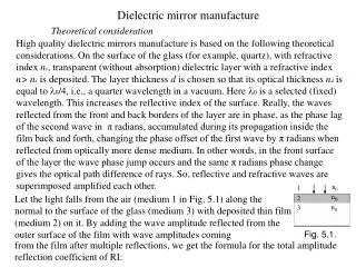
A comparison of optical trains based on a GIMM or a Dielectric Mirror final optic. HAPL San Diego, 9th Aug. 2006. Malcolm W. McGeoch. PLEX LLC 280 Albany St. Cambridge MA 02139 617-621-6300. Baseline HAPL final optical parameters:

E N D
A comparison of optical trains based on a GIMM or a Dielectric Mirror final optic HAPL San Diego, 9th Aug. 2006 Malcolm W. McGeoch PLEX LLC 280 Albany St. Cambridge MA 02139 617-621-6300
Baseline HAPL final optical parameters: 2.5MJ at 5Hz, 40 illumination beams each 62.5kJ 2 Jcm-2 in optical distribution ducts. Duct aspect ratio 6:1, each beam 3x18 beamlets (area of one beam = 3x18x(0.24)2 = 3.1m2) 4. Focal length 39m (GIMM) or 42m (all-Dielectric case) Vertical “slits” in blanket, total 0.6% of 4p (slit size 1.35m high x 0.22m wide for GIMM case) 24cm x 24cm beamlet from de-multiplex array
The final optics must function to attenuate the neutron flux: target 3x1024 /beamline /FPY n laser building < 1x10¹⁹ /beamline /FPY = < 1mrem/hr/day at one day after shutdown (M. Sawan, this meeting) Attenuation factor of 106 !
We can encase the optical path with 1.5m - 3m of concrete and attenuate using the angles that are needed in any case for distribution around the sphere target n 3x1024 neutrons/beamline /FPY < 1x10¹⁹ /beamline /FPY Concrete + ferritic steel + H2O coolant
40 port arrangement: 3 tiers, 8 longitudes each hemisphere View from above “North Pole” Elevation
Uniformity for 9-element “basket”: N = 3,4,5 with g = 0.8, 0.9, 1.0
Elevation sketch of beams for all-dielectric final optics (3J cm-2)
Plan sketch of beams in one quadrant for all-dielectric final optics
Radiation loads in all-dielectric design Mirror location total n/FPY/cm2 n >0.1MeV/cm2 n>1MeV/cm2 gamma/cm2 M1 32.5m from target 2.3e20 2.3e20 2.3e20 8e19 M2 9.5m from M1 6e17 4.5e17 3.5e17 3e17 M3 15.5m from M2 1e16 5e15 3e15 1e16 M4 1.6m from M3 2e14 3e13 1.5e13 2e14 M4 6m from M3 2e13 2e12 1e12 2e13 Estimates courtesy of M. Sawan.
Radiation resistance of multilayers compared to requirements Category: layer mixing reflectivity damage resistance Dose: 1e19cm-2 OK OK (vis*) ? (4% of FPY) 1e20cm-2 OK anneal? ? (44% of FPY) 1e21cm-2 4nm? anneal? ? (4 FPY) *I. I Orlovskiy and K. Yu. Vukolov, “Thermal and neutron tests of multilayered dielectric mirrors” Fus. Eng. Des. 74, 865-869 (2005)
Layer mixing? (248nm mirror layers are about 35nm thick) Mixing of layers was thought (*) to be a showstopper for dielectric mirrors, but data on irradiated multilayers for X-ray optics and superconductors eases this concern (*) R. L. Bieri and M. W. Guinan, “Grazing incidence metal mirrors as the final elements in a laser driver for inertial confinement fusion”, Fusion Technology 19 673-678 (1991).
Exposure of XUV mirrors to 1.1e19cm-2 (1-2MeV neutrons) low index: Si or B4C, or C high index: Mo or W N bilayers “d” spacing S. P. Regan et al. “An evaluation of multilayer mirrors for the soft X ray and extreme ultraviolet wavelength range that were irradiated with neutrons” Rev. Sci. Instrum. 68(1), 757-760 (1997)
XUV mirrors tested by Regan et al. (exposure temp 270-300C) Composition “d” (nm) substrate N Mo/Si 8.78nm Zerodur 50 W/B4C 2.28nm Si wafer 100 W/C 2.53nm Si wafer 100 Mo/Si 18.7nm Si wafer 25 Results: Mo/Si mirrors had slight shift in peak L and slight reflectivity decrease, exactly consistent with 270-300C known thermal effects. W mirrors had opposite shift in peak L and slight increase in reflectivity, again consistent with known thermal effects. No effects attributable to fast neutron exposure of 1.1e19cm-2 (10-2 dpa/atom)
Layered superconductors have been tested for fusion reactor use 2nm AlN layers 9 - 26nm NbN layers (not to scale) 20 bilayers R. Herzog et al. “Radiation effects in superconducting NbN / AlN multilayer films” J. Appl. Phys. 68, 6327-6330 (1990). Results: Jc>108Am-2 at 4.2K and 20T, before and after irradiation No degradation of 2nm AlN layers at 1x10¹⁹ neutrons/cm2 (>0.1MeV)
Lack of layer mixing is consistent with expectations XUV reflectivity and enhanced Jc are both sensitive to the roughness of the surfaces of layers, and the above results both indicate less than about 1nm of induced roughness after irradiation to 10-2 dpa. Bieri and Guinan (*) estimated mixing of roughly 3nm/(dpa)1/2, where 1dpa = 5x10²⁰ (14MeV) n/cm2 for most dielectrics For “low” doses (much less than1 dpa), this diffusion approach does not apply (for example, at 10-2 dpa, 99% of layer remains undisturbed). A more critical test will occur at > 0.1dpa (5x10¹⁹ neutrons cm-2) (20% of FPY) (*) R. L. Bieri and M. W. Guinan, “Grazing incidence metal mirrors as the final elements in a laser driver for inertial confinement fusion”, Fusion Technology 19 673-678 (1991).
Dielectric mirrors are being evaluated for the final optic 30 layers = 1.9µm …short absorption path Neutron-stable sapphire substrate 500C anneal cycle removes neutron-induced absorption
Neutron irradiation produces optical absorption in dielectrics
248nm neutron-induced absorption is annealed out at 500C Sample 0.6cm SiO2, 6.6e20 neutrons cm-2. --> post anneal loss in 2µm dielectric path is negligible Data from J. Latkowski, HAPL meeting, Rochester, Nov. 2005
Planned neutron irradiation of mirrors All the reported multilayer exposures have been to about 1019/cm2 The key near term need is for exposure to 1020/cm2 (44% FPY) A variety of KrF mirrors and GIMM quality aluminum mirrors will be exposed to up to 1021 neutrons cm-2 at ORNL (>1FPY). Some mirrors will be irradiated at high temperature (250C and 500C) (K. J. Leonard et al. 14th laser IFE progm. wkshp, ORNL, March 2006)
GIMM design options (slide courtesy M. Sawan) • Two options considered for GIMM materials and thicknesses • Both options have 50 microns thick Al coating • Option 1: Lightweight SiC substrate • The substrate consists of two SiC face plates surrounding a SiC foam with 12.5% density factor • The foam is actively cooled with slow-flowing He gas • Total thickness is 1/2" • Total areal density is 12 kg/m2 • Option 2: Lightweight AlBeMet substrate • The substrate consists of two AlBeMet162 (62 wt.%Be) face plates surrounding a AlBeMet foam(or honeycomb) with 12.5% density factor • The foam is actively cooled with slow-flowing He gas • Total thickness is 1" • Total areal density is 16 kg/m2
Radiation loads in SiC GIMM design 5Jcm-2 Mirror location total n/FPY/cm2 n >0.1MeV/cm2 n>1MeV/cm2 gamma/cm2 GIMM(M1)24m from target 4.2e20 4.0e20 3.6e20 1.4e20 M2 14.9m from M1 1.0e18 9e17 8e17 4e17 M3 1.6m from M2 2e16 6e15 2.8e15 1.3e16 M3 6m from M2 2e15 4e14 2e14 1.3e15 Estimates courtesy of M. Sawan.
Unknowns remain for both the GIMM and dielectric approaches: After neutron exposure: Laser-induced damage has not been measured in either case Reflectivity at 248nm (KrF) has not been measured in either case Substrate optical quality has not been measured (except to 1019 cm-2) Other considerations: The GIMM requires polarized light => less random illumination The GIMM area is 14m2 vs dielectric area 1.9m2 => cost is high The neutron maze is much more effective in the dielectric case