Download
1 / 31
320 likes | 506 Views
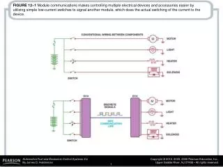
FIGURE 12–1 Module communications makes controlling multiple electrical devices and accessories easier by utilizing simple low-current switches to signal another module, which does the actual switching of the current to the device.

E N D
FIGURE 12–1 Module communications makes controlling multiple electrical devices and accessories easier by utilizing simple low-current switches to signal another module, which does the actual switching of the current to the device.
FIGURE 12–2 A network allows all modules to communicate with other modules.
FIGURE 12–3 A ring link network reduces the number of wires it takes to interconnect all of the modules.
FIGURE 12–4 In a star link network, all of the modules are connected using splice packs.
FIGURE 12–5 A typical BUS system showing module CAN communications and twisted pairs of wire.
FIGURE 12–6 UART serial data master control module is connected to the data link connector at pin 9.
FIGURE 12–7 The E & C serial data is connected to the data link connector (DLC) at pin 14.
FIGURE 12–8 Class 2 serial data communication is accessible at the data link connector (DLC) at pin 2.
FIGURE 12–9 Keyword 82 operates at a rate of 8,192 bps, similar to UART, and keyword 2000 operates at a baud rate of 10,400 bps (the same as a Class 2 communicator).
FIGURE 12–11 A twisted pair is used by several different network communications protocols to reduce interference that can be induced in the wiring from nearby electromagnetic sources.
FIGURE 12–12 A CANDi module will flash the green LED rapidly if communication is detected.
FIGURE 12–13 A Ford OBD-I diagnostic link connector showing that SCP communication uses terminals in cavities 1 (upper left) and 3 (lower left).
FIGURE 12–14 A scan tool can be used to check communications with the SCP BUS through terminals 2 and 10 and to the other modules connected to terminal 7 of the data link connector (DLC).
FIGURE 12–15 Many Fords use UBP module communications along with CAN.
FIGURE 12–16 CCD signals are labeled plus and minus and use a twisted pair of wires. Notice that terminals 3 and 11 of the data link connector are used to access the CCD BUS from a scan tool. Pin 16 is used to supply 12 volts to the scan tool.
FIGURE 12–17 The differential voltage for the CCD BUS is created by using resistors in a module.
FIGURE 12–18 Many Chrysler vehicles use both SCI and CCD for module communication.
FIGURE 12–19 CAN uses a differential type of module communication where the voltage on one wire is the equal but opposite voltage on the other wire. When no communication is occurring, both wires have 2.5 volts applied. When communication is occurring, CAN H goes up 1 volt to 3.5 volts and CAN L goes down 1 volt to 1.5 volts.
FIGURE 12–20 A typical (generic) system showing how the CAN BUS is connected to various electrical accessories and systems in the vehicle.
FIGURE 12–21 A DLC from a pre-CAN Acura. It shows terminals in cavities 4, 5 (grounds), 7, 10, 14, and 16 (B+).
FIGURE 12–22 A Honda scan display showing a B and two U codes, all indicating a BUS-related problem(s).
FIGURE 12–23 A typical 38-cavity diagnostic connector as found on many BMW and Mercedes vehicles under the hood. The use of a breakout box (BOB) connected to this connector can often be used to gain access to module BUS information.
FIGURE 12–24 A breakout box (BOB) used to access the BUS terminals while using a scan tool to activate the modules. This breakout box is equipped with LEDs that light when circuits are active.
FIGURE 12–25 This Honda scan tool allows the technician to turn on individual lights and operate individual power windows and other accessories that are connected to the BUS system.
FIGURE 12–26 Modules used in a General Motors vehicle can be “pinged” using a Tech 2 scan tool.
FIGURE 12–27 Checking the terminating resistors using an ohmmeter at the DLC.
FIGURE 12–28 Use front-probe terminals to access the data link connector. Always follow the specified back-probe and front-probe procedures as found in service information.
FIGURE 12–29 (a) Data is sent in packets, so it is normal to see activity then a flat line between messages. (b) A CAN BUS should show voltages that are opposite when there is normal communications. CAN H circuit should go from 2.5 volts at rest to 3.5 volts when active. The CAN L circuit goes from 2.5 volts at rest to 1.5 volts when active.
FIGURE 12–30 A 16 pin OBD-II DLC with terminals identified. Scan tools use the power pin (16) and ground pin (4) for power so that a separate cigarette lighter plug is not necessary on OBD-II vehicles.
FIGURE 12–31 This schematic of a Chevrolet Equinox shows that the vehicle uses a GMLAN BUS (DLC pins 6 and 14), plus a Class 2 (pin 2) and UART.


![模块一 [Modules 1 - 5, Book 7A] 模块二 [Modules 6 - 10 , Book 7A] 模块三 [Modules 1 - 6 , Book 7 B ]](https://cdn3.slideserve.com/5458553/slide1-dt.jpg)