Download
1 / 32
320 likes | 422 Views
CIRCULAR ACCELERATOR VI. COLLECTIVE EFFECT I, LONGITUDINAL. COASTING BEAM FIELD CREATED BY THE BEAM (LONGITUDINAL WALL IMPEDANCE) LINEAR CHARGE DENCITY l I=e lb c. e lb c. E r. b. BEAM. a. B f. B f. I W =I(AC) BEAM. - - - - - - - - - - - - - - - - - - - - - - - - - - -.

E N D
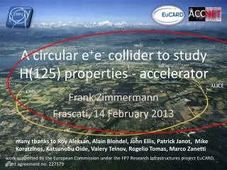
CIRCULAR ACCELERATOR VI COLLECTIVE EFFECT I, LONGITUDINAL
COASTING BEAM FIELD CREATED BY THE BEAM (LONGITUDINAL WALL IMPEDANCE) LINEAR CHARGE DENCITY l I=elbc elbc Er b BEAM a Bf Bf
IW=I(AC)BEAM - - - - - - - - - - - - - - - - - - - - - - - - - - - Er(s) Er(s+Ds) + + + + + + + + + + + + + + + + + + + + + + + + + + + + + + + + + + + + + + + + + + + + + + + + + + + + + + - - - - - - - - - - - - - - - - - - - - - - - - - - -
INDUCTIVE WALL Inductance per unit length And total voltage particle sees per turn is where Lets assume disturbance in line density is in the form N; number of waves peer turn disturbance
Reactive(imaginary) impedance due to Space charge and wall inductance Note, the space charge term is capacitive and opposite to wall inductance RESISTIVE WALL For smooth wall(no bellows or flanges), due to the skin effect, there are equal amount of real(resistive) and imaginary(inductive) impedance and where ; conductivity : permiability
IN GENERAL The impedance of the ring is complicated issue and the voltage acting on the beam can be represented :complex and the voltage acting on the beam is represented CASE WITHOUT ENERGY SPREAD (NEGATIVE MASS INSTABILITY) Take space charge field only Take At A energy gain At B energy loss l A B s
Suppose we take small disturbance in a coasting beam in form of This will create a energy disturbance and frequency change in form of Voltage seen by the beam is And energy change
And since or Continuity of current requires or and
By carrying the calculation through From previous page substituting Is complex and Is imaginary frequency shift Disturbance either grow or damped depending on sign If Is real No growth of disturbance but the frequency differ by from Is complex then instability Growth time is
Is purely reactive If If Is positive (capacitive, ie space charge) Real below transition and stable Imaginary above transition and unstable NEGATIVE MASS INSTABILITY Is negative then it’s the other way around Has resistive part then there will be imaginary part and There is instability RESISTIVE WALL INSTABILITY
Z imag Z real
BEAM WITH ENERGY SPREAD Consider the beam distributed uniformly in q with finite energy width again Lets start with Lousville’s theorem, it says for canonical conjugate variable q and w the phase space density g does not change where For observer in laboratory this can be rewritten Vlasov Equation Approximate the equation by and
Lets assume the Vlasov equation has a solution in a form Substituting to the equation or Multiplying ebc/R and integrating over E since
If W lies within the distribution nw of the particles, denominator of the integral vanishes and the integral split into the principal value and residue Beam response is Which has real and imaginary part Real part actually absorb energy and damping the disturbance the energy goes to individual particle in the beam LANDAU DAMPING For self generated field disturbance
F(x) S ; half width at half maximum in w distribution X ; dimensionless variable X1 ; dimensionless variable We also define distribution function s w also X=1 Now the dispersion relation becomes +1 below transition -1 above transition
Here Z is complex and the coefficient can be represented in general Therefore Relationship between V’U’ and x1 X1 is related to frequency shift Area inside the curve for in V’U’ plain is stable and approximate to a Circle and can write stability condition KEIL-SCHNELL STABILITY CRITERION
t t BUNCHED BEAM Synchrotron motion (b) (a)
(c) Quad mode (a) Distribution (b) Dipole mode Unlike electrons the bunch distribution is not Gaussian but bell shaped and Many people uses parabolic shape And charge density is
field induced by bunched beam The bunched beam can be represented by Fourier expansion If the induced wall current does not Decay before next bunch arrives INSTABILITY OCCURE Such a place is usually some sort of cavity and let : resonant freq, :shunt impedance Q :quality factor
frequency frequency For dipole mode we can integrate and Capacitive Resistive inductive ROBINSON INSTABILITYsingle bunch phenomena On top of usual phase oscillation, there is impedance driven oscillation Below transition and Higher energy Lower energy impedance Energy loss Impedance driven phase oscillation get damped Reverse happen and anti-damps INSTABILITY If REVERSE IS TRUE ABOVE TRANSITION
For bunch current driving this cavity Phase error due to the phase oscillation For small or The real voltage induced in the cavity is R’s are resistive impedances at the frequencies This will react back to the beam Average over all particles
This has to be added to original energy derivative equation Say Now one has to add Vb to this equation The term with Ro is constant and compensated by RF equation of motion For the synchrotron motion becomes A solution of the equation is with And below transition stable
COUPLED BUNCHES SINGLE BUNCH OSCILATION OCCURES WITH ROSONATOR BUT COUPLED BUNCH CAN BE CAUSED BY RATHER BROAD BAND WITH IMPEDANCES The mode of oscillation is equal to the number of bunches For example take a dipole oscillation of 4 bunches Bunch 1 Bunch 2 Bunch 3 bunch4 There are 4 independent mode of oscillation we label n corresponding to
Below transition mod 1 is unstable 2 4 is neither stable nor unstable Above transition mod 3 ““““ If there is only two bunches in the ring instability neither grow nor damp No instability The growth rate is Number of equidistant bunches Harmonic number Total current Bunchin factor x full bunch length in seconds Form factor efficiency which couples resonator and the mode Factor depend on Q of the resonator, mode number and resonant frequency
Landau Damping The spread of phase oscillation frequency S is from the none-linearity of the RF wave form and approximately Stability condition is SPACE CHARGE AND INDUCTIVE WALL IMPEDANCE The voltage seen by a particle is ignoring the space charge force This to be added to the equation of motion Above transition it will lengthen the bunch Below transition it will shorten the bunch
Lets take parabolic distribution of the bunch Number in the bunch Full bunch length for This distribution is good approximation for protons but not for electrons Total voltage seen by particle inside the bunch is
Since effectively reduce the RF slope the incohernt synchrotron frequency is changed by A coherent motion does not change If the coherent motion frequency moves outside of incoherent frequency Landau damping does not work This is true for above transition the space charge effect is small But below transition the space charge impedance is capacitive and tend to Cancel inductive impedance
MICROWAVE INSTABILITY There are many papers in this subject but no set theory If the frequency of the instabilities are much higher than RF frequency we may use the coasting beam criteria Keil-Schnell criteroin since Higher RF voltage reduces this microwave instbilities