Download
1 / 21
210 likes | 398 Views
Efficient On-Line Testing of FPGAs with Provable Diagnosabilities. Vinay Verma (Xilinx Inc. ) Shantanu Dutt (Univ. of Illinois at Chicago) Vishal Suthar (Univ. of Illinois at Chicago). Outline. Previous on-line testing methods

E N D
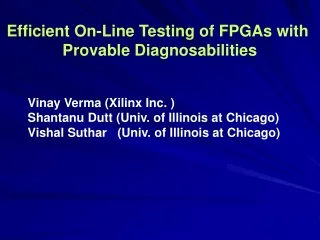
Efficient On-Line Testing of FPGAs with Provable Diagnosabilities Vinay Verma (Xilinx Inc. ) Shantanu Dutt (Univ. of Illinois at Chicago) Vishal Suthar (Univ. of Illinois at Chicago)
Outline • Previous on-line testing methods • Roving Tester (ROTE) & Bulilt-in Self Tester (BISTer) Concepts • Two new BISTer architectures • 1-diagnosable BISTer-1 • 2-diagnosable BISTer-2 • New fast functional testing and diagnosis: FAST-TAD • Simulation results (fault coverage and fault latency) • Conclusions
Previous On-Line Testing Methods • On-line testing: Testing a (small) part of the FPGA while a circuit is executing on another part – increases system availability • Fault scanning technique of [Shnidman et al., IEEE Tr. VLSI’98] that is applicable to bus-based FPGAs • STAR technique of [Abramovici, et al., ITC’99] that uses a roving tester that tests part of the FPGA while the rest executes the application circuit. • Their group have presented several Built-in-Self-Testers (BISTers) with different diagnosabilities and complex adaptive diagnosis; e.g., [Abramovici, et al., ITW’00] – will be discussed later • Have also presented on-line BIST for interconnects [Stroud et al., ITW’01]
Roving Tester (ROTE) with Built-in-Self-Testers (BISTers) CUT TPG ORA CUT Syndrome BISTer • Two column left spare for • ROTE; one for fault reconf. • ROTE roves across the FPGA • ROTE concept similar to STAR • at a high level • Differentiation: • BIST designs, • fault reconfig. & incr. re-routing • techniques BISTer ROTE SPARECOLUMN SPARECOLUMN TPG - Test Pattern Generator CUT - Cells Under Test ORA - Output Response Anal. CIRCUIT CIRCUIT CIRCUIT
Definitions k-diagnosability: A testing technique is said to be k-diagnosableif in the presence of any m ≤ k faulty components it can correctly identify all m faulty components among the n ≥ k components that it tests. Detailed syndrome: The detailed syndrome for a session is the 0/1 bit pattern observed at the ORA output (0 => match, 1 => mismatch) over all the test vectors of the TPG. Gross syndrome: A gross syndrome of a session is the overall pass/fail (indicated as X/√) observation over all modes of operation for that session. In other words, the gross syndrome of a session is a X (fail) if the ORA output is 1 for any input test vector and is a √ (pass), otherwise. CUT TPG ORA CUT Syndrome BISTer
BISTer-0[M. Abramovici et. al., ITC ’99] A D A D TPG CUT CUT ORA CUT TPG ORA CUT C B B C (S2) (S1) • Exhaustive testing of CUTs • S1, S2, S3, S4 are four sessions • of testing in a BISTer tile A A D D CUT TPG ORA CUT ORA CUT CUT TPG B C B C (S4) (S3) TPG - Test Pattern Generator CUT - Cells Under Test ORA - Output Response Analyser
BISTer-0[M. Abramovici et. al., ITC ’99] Theorem: BISTer-0 is zero-diagnosable. Proof: The same pair of PLBs are configured as CUTs in two different sessions: PLBs A and C in S2 and S4 PLBs B and D in S1 and S3. When either PLB fails, the gross syndrome will be identical in these sessions. E.g. if A fails as a CUT only, then its gross syndrome is identical to the gross syn. of C failing as a CUT only. Hence we cannot distinguish between faulty PLBs A and C. Thus has a complex adaptive diagnosis phase
Our BISTer-1 Architecture A B CUT TPG TPG ORA A B C CUT ORA D CUT C CUT D Sess PLB S1 S2 S3 S4 A TPG ORA CUT CUT B CUT TPG ORA CUT C CUT CUT TPG ORA D ORA CUT CUT TPG
Our BISTer-1 Architecture Sess PLB S1 S2 S3 S4 A TPG ORA CUT CUT B CUT TPG ORA CUT C CUT CUT TPG ORA CUT CUT D ORA CUT CUT TPG Each PLB is a CUT in 2 unique sessn’s and a TPG in another unique session – this serves to uniquely identify the faulty PLB which will have a X X √ in these sessions. Theorem: BISTer-1 is 1-diagnosable
BISTer-2 Architecture B A CUT TPG C F ORA 2 ORA 1 Y1 Y2 E D TPG CUT Y1 – output of the ORA comparing CUTs Y2 – output of the ORA comparing TPGs Theorem: BISTer-2 is 1-diagnosable Proof: Gross syndrome corresponding to Y1 for each faulty PLB is unique. E.g. Y1 is pass in section 2 only for faulty PLB A and no other PLB. Gross syndrome corresponding to Y1 6 rotations => 6 sessions
BISTer-2 Architecture (cont.) dist. 3 pair B A B A CUT TPG TPG OR2 Y2 dist. 1 pair C F C F TPG CUT OR2 OR1 Y1 Y2 E D E D CUT OR1 Y1 TPG CUT (S2) dist. 2 pair B A OR1 CUT Y1 F C TPG CUT E D OR2 TPG Y2 (S6) • Theorem: BISTer-2 is 2-diagnosable under the assumptions: • 1. No fault masking for all detailed syndromes • 2. Faulty PLBs either uniformly all fail or all pass as TPG/ORA • Proof: • For the case faulty PLBs fail as TPG/ORA also, possible gross syndromes (GS) are: Y1Y2 = X √ and XX • Class 1: faulty pairs corresponding to GS= X √. • 3 Class 1 pairs: (CUT,CUT)2, (CUT,OR1)1 and (OR1,CUT)1 • Class 2 includes remaining faulty pairs (GS=XX). • For session S1, Class 1 includes BD2, BC1 and CD1 (S1) Class 1 pairs Class 1 pairs BC only Class 1 pair from S1 S1: GS =X X => Class 2 pairs S1: GS =X √ => BC/CD/BD S2: GS =X X => BC/BD S2: GS =X √ => CD S6: GS =X X => BD In S1-S6 all the faulty pairs at dist. 1 & 2 will be in Class 1 and hence will be diag. S6: GS =X √ => BC CD only Class 1 pair from S1 => GS’s are distinct for all dist. 1 & 2 faulty pairs
BISTer-2 Architecture (cont.) A B OR2 TPG Y2 C F CUT TPG E D OR1 CUT Y1 (S3) Three dist. 3 pairs B A For faulty pairs at dist. 3, i.e., pairs AD, BE and CF, G.S. of Y1Y2 = XX in all sessions. Hence they don’t fall in Class 1 and hence are not distinguishable among themselves. To distinguish these dist. 3 pairs we compare their detailed syndromes: AD: dS1 = dS3 (T-C in both sess’s), dS4 = dS6 (C-T in both) Similarly, BE: dS1 = dS5, dS2 = dS4 CF: dS2 = dS6, dS3 = dS5 These pairs are uniquely diag. except for the case when dS1 = dS3 = dS5 and dS2 = dS4 = dS6; which is a very low probability event---e.g. requires 4 v. low prob. events of the type ds(CUT, TPG) = ds(TPG, CUT) Thus all faulty pairs are diagnosable with high probability. CUT TPG F C OR2 OR1 Y1 Y2 D E TPG CUT (S1) The detailed syndrome for a session is the 0/1 bit pattern observed at the ORA output (0 => match, 1 => mismatch) over all the test vectors of the TPG.
Fast-TAD: A Fast Functional Testing and Diagnosis c1 c1 c2 c2 c7 c6 c5 ROTE ROTE ROTE ROTE • In this methodology a PLB is tested only for specific functions (called operational functions) it will assume as the ROTE moves across the FPGA. • A PLB X is functionally-faulty (f-faulty) if faults in X produce incorrect outputs, • when X implements any of its operational functions. • Property:While roving the ROTE in an FPGA either without f-faults or with • reconfigured f-faults, a PLB X needs to implement at most 2 functions: its original function (when ROTE is in its initial position) and the fn. of the PLB two f-fault-free PLBs to its right. Operational functions of c3 • Advantages: • Faster T&D • >> yield • >> availab. c7 c6 c3 c5 c4 fx1 fx2 fx3 fx4 c2 c1 c7 c6 c4 c3 c5 fx4 fx3 fx4 fx3 fx1 fx2 PLB in column c3 implements functions fx1 and fx3 as the ROTE moves across the FPGA.
Diagnosis in Fast-TAD (overlaid on BISTer-1) • Each PLB is tested in its two operational fn. • A f-faulty PLB Q config. as a TPG will have • a GS of √while Q configured as a CUT & • performing its oper. functions will have GS • of X. In all other cases GS is either a √ or a X Theorem: Fast-TAD using BISTer-1 is 1-diagnosable • In some cases, faults in A and C ( or B and D) • may not be distinguishable – a 2nd test reqd. • Require 10.t1 time versus 16.t1 if both CUTs • in a session are config. both their oper fns.
Legend: 1 2 Center faulty PLB Correlated faulty PLB Non-faulty PLB Simulation Environment • A 32 x 32 FPGA was simulated with 3-input 1-output PLBs. • Fast-TAD with BISTer-1 and STAR BISTer (enhancement of BISTer-0 with • 1-diagnosability) techniques were implemented on this FPGA. • The adaptive diagnosis phase of the STAR BISTer is very complex; we • have simulated only the fault detection and direct diagnosis phase of the • STAR BISTer (BISTer-1 has no adaptive diagnosis phase) • Two types of faults (with internal fault density up to 25%) were inserted: • 1. Randomly distributed faults with external faulty density up to 40% • 2. Clustered faults with cluster density up to 3% Prob. of a fault around a “center” fault = k/d (k=const, d=distance)
Simulation of 3 x 2 STAR BISTer[M. Abramovici et, al., ITW ’00] T – TPG, O – ORA, C – CUT • 1-diagnosable; it can diagnose 1 fault in a • 3 x 2 BISTer area (1 / 6). • Each BISTer consists of 3 TPGs, 2 CUTs • and 1 ORA – 6 sessions reqd. • STAR moves by 2 cols • Very complex adaptive diagnosis phase Version of our 2 x 2 BISTer-1 w/ a 3-PLB TPG • # of TPG PLBs = ratio of inps/outps in PLB • => 3 TPGs for testing 3-inp1-outp PLBs • 2x3 BISTer-1: 3 TPGs, 2 CUTs & 1 ORA • Basically two partially overlapped basic 2x2 BISTer-1’s – 8 sessions reqd. • ROTE moves by 2 cols • Result: Can diagnose up to 1 fault in every alt. col of a 2-row FPGA subarray – diagnosability is thus 1 / 4 approaching that of ideal Bister-1’s
Clustered faults with k = 0.5 in The three values of fault density in the plot correspond to cluster densities of 1%, 2% and 3% respectively. Results: Fault Coverage v/s Fault Density Randomly distributed faults
Conclusions • Developed a 1-diag. (1 of 4) BISTer • Developed (for the 1st time) a 2-diag. (2 of 6) – w/ high prob. -- BISTer • Developed (for the 1st time)functional T&D: tests PLBs in only 2 funcs that they will perform; prev. methods performed exhaust testing • Fast-TAD w/ BISTer-1 has the samediagnosability (1 of 4) for f-faults • Our methodsdo not require adaptive diagnosis;previous techniques have complex adaptive diag. mechanisms • Simulation results forFast-TAD w/ BISTer-1: • fault coverages of 96% & 92 % at fault densities of 10% & 20% resp. • The previous bestSTAR-2x3-BISTer (non-adaptive version):coverages of 74% & 46% at these densities • Much lower fault latencyof Fast-TAD w/ BISTer-1 compared to that of the STAR-3x2-BISter • Its high fault coverage at high flt. densities and low fault latency should proveuseful for testing and diagnosing emerging tech. FPGAs (<= 90 nm, nanotechnology)that are expected to have high fault densities
BISTer-2 architecture B A CUT TPG C F ORA 2 ORA 1 Y1 Y2 E D TPG CUT Y1 – output of the ORA comparing CUTs Y2 – output of the ORA comparing TPGs Theorem: BISTer-2 is 1-diagnosable Proof: Gross syndrome corresponding to Y1 for each faulty PLB is unique. E.g. Y1 is pass in section 2 only for faulty PLB A and no other PLB. OR1 => ORA 1 (Y1) OR2 => ORA 2 (Y2) Gross syndrome corresponding to Y1