Download
1 / 8
90 likes | 335 Views
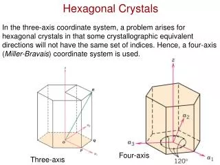
This guide explains how to draw views of a cut hexagonal prism, including end elevation, surface development, and true shape, along with detailed steps to identify, draw, and finish the different views.

E N D
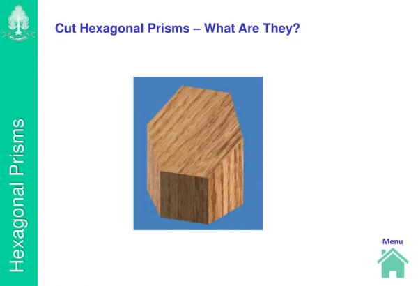
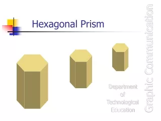
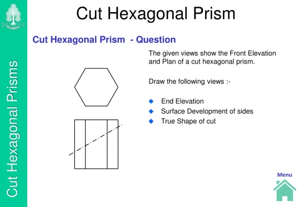
Cut Hexagonal Prism Cut Hexagonal Prism - Question • The given views show the Front Elevation and Plan of a cut hexagonal prism. • Draw the following views :- • End Elevation • Surface Development of sides • True Shape of cut
Finding Position of End Elevation Project the outline of the End Elevation from the Front Elevation and the Plan.
Identifying the Generators Number each of the points on each of the views. 1 2 6 3 5 4 3 /6 4 /5 /4 1 /5 2 1 /2 6 3
1 2 6 3 5 4 3 /6 4 /5 /4 1 /5 2 1 /2 6 3 Finding Cut Surface on End Elevation Project from the cutting line on the Elevation to find the cut points on the End Elevation. Join each of the points to find the cut shape on the End Elevation
1 2 6 3 5 4 3 /6 4 /5 /4 1 /5 2 1 /2 6 3 Drawing the Development To draw the Development of the sides of the prism, project the base line and the height from the Front Elevation. Draw a vertical generator to indicate where the Development will start, and then step out the width for the six sides. Draw generators through each of these points. Number each of the generators starting with either the highest point or the lowest point. Project each of the cut points from the Elevation onto the appropriate Development generator and draw straight lines to indicate the shape of the Development. 6 1 3 2 4 5 6
1 2 6 3 5 4 3 /6 4 /5 /4 1 /5 2 1 /2 6 3 Drawing the Development Darken the outlines of the Development. Add ‘fold lines’ to the Development to indicate where the corners are. 6 1 3 2 4 5 6
1 2 6 3 5 4 3 /6 4 /5 /4 1 /5 2 1 /2 6 3 6 1 3 2 4 5 6 3 4 6 5 1 2 3 Drawing the True Shape of the Cut To find the True Shape, project the cut points away from the Front Elevation at right angles to the cut. 2 Draw a datum line on the True Shape parallel to the cut line of the Front Elevation and at right angles to the lines just projected. Also add a datum line to the plan. 3 1 4 Measure the vertical distances from the datum to each of the cut points. Transfer these sizes onto the True Shape. 6 5
2 3 1 1 2 4 6 6 3 5 5 4 3 /6 4 /5 /4 1 /5 2 1 /2 6 3 6 1 3 2 4 5 6 3 4 6 5 1 2 3 Finishing the Drawing To finish the drawing darken the outlines of the True Shape