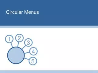
Circular profiles
Circular interpolation. Circular profiles. Circular cutting motion Arc or Radius Cutting is known as Circular interpolation Milling machine operations involve circular motion for determining tool movement in the clockwise direction as well as the counterclockwise direction.


Circular profiles
E N D
Presentation Transcript
Circular interpolation Circular profiles
Circular cutting motion • Arc or Radius Cutting is known as Circular interpolation • Milling machine operations involve circular motion for determining tool movement in the clockwise direction as well as the counterclockwise direction. • Circular interpolation is carried out with Go2 or G03 code • Circular interpolation can be programed using radius (R ) value or (I J K) value
Circular interpolation using Radius • General format for G02 or G03 • X Y R • G02 X8.25 Y 4.25 R 1.5 • Go2 means that it will be clockwise circular cut • X value 8.25 • Y value is 4.25 • R value is 1.5 is the length of radius
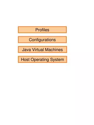
Tool Motion • Plane Selection: • G17 XY plane • G 18 XZ plane • G19 YZ plane
The general format is: G02 X8.25 Y 4.25 R 1.5 Programing Circular move
G17 G90 G2 X 2.125 Y 0.75 R5 F2 Example
To maintain constant feed rate while profiling a contour: Distance traveled at the center of the tool Feed rate of the tool center: linear motion In circular motion Page:199 Profiling at constant Feed Rate
G17 G91 G2 X 4.125 Y 2.125 R - 5 F2 Example
Heading of Program Plane Selection Tool Selection The system in in proper motion mode(G90, G91) The control in linear interpolation mode (G0 G1) Feed rate and speed has been specified (F,S) Circular Interpolation Direction ( G02 , G03) Program