Download

1 / 36
360 likes | 606 Views
Programming Examples that Expose Efficiency Issues for the Cell Broadband Engine Architecture. William Lundgren ( wlundgren@gedae.com , Gedae ), Rick Pancoast (Lockheed Martin), David Erb (IBM), Kerry Barnes ( Gedae ), James Steed ( Gedae ) HPEC 2007. Introduction.

E N D
Programming Examples that Expose Efficiency Issues for the Cell Broadband Engine Architecture William Lundgren (wlundgren@gedae.com, Gedae), Rick Pancoast (Lockheed Martin), David Erb (IBM), Kerry Barnes (Gedae), James Steed (Gedae) HPEC 2007
Introduction • Cell Broadband Engine (Cell/B.E.) Processor • Programming Challenges • Distributed control • Distributed memory • Dependence on alignment for performance • Synthetic Aperture Radar (SAR) benchmark • Gedae is used to perform the benchmark • If programming challenges can be addressed, great performance is possible • 116X improvement over quad 500MHz PowerPC board
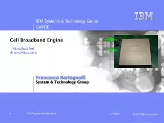
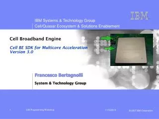
Cell/B.E. Architecture • Power Processing Element (PPE) • Eight Synergistic Processing Elements (SPE) • 4 SIMD ALUs • DMA Engines • 256 kB Local Storage (LS) • System Memory • 25 GB/s • Element Interconnect Bus (EIB) • Over 200 GB/s
Gedae Addresses the Software Architecture • Software architecture defines how software is distributed across processors like the SPEs • Optimizing the software architecture requires a global view of the application • This global view cannot be obstructed by libraries
Gedae’s Approach is Automation • The functional specification is specified by the programming language • The implementation specification defines how the functionality is mapped to the HW (i.e., the software architecture) • Automation, via the compiler, forms the multithreaded application Functional Specification Implementation Specification Compiler Threaded Application Multicore Hardware Thread Manager Vector & IPC Libraries www.gedae.com
Stages of SAR Algorithm • Partition • Distribute the matrix to multiple PEs • Range • Compute intense operation on the rows of the matrix • Corner Turn • Distributed matrix transpose • Azimuth • Compute intense operation on the rows of [ M(i-1) M(i) ] • Concatenation • Combine results from the PEs for display
Stages Execute Sequentially Range processing Distributed Transpose Azimuth processing
SAR Performance • Platforms used • Quad 500 MHz PowerPC AltiVec Board • IBM QS20 Cell/B.E. Blade Server (using 8 SPEs at 3.2 GHz) • Comparison of large SAR throughput • Quad PowerPC Board 3 images/second • IBM QS20 347.2 images/second • Maximum achieved performance on IBM QS20
Synthetic Aperture Radar Algorithm Tailoring to the Cell/B.E.
Processing Large Images • Large images do not fit in LS • Size of each SPE’s LS: 256 kB • Size of example image: 2048 x 512 x 4 B/w = 4 MB • Store large data sets in system memory • Coordinate movement of data between system memory and LS System Memory 256 MB on Sony Playstation 3 1 GB on IBM QS20 LS LS LS LS LS LS LS LS 25GB/s
Strip Mining • Strip mine data from system memory • DMA pieces of image (rows or tiles) to LS of SPE • Process pieces of image • DMA result back to system memory Data for Processor 0 Data for Processor 1 System Memory Data for Processor 2 LS SPU … SPE 0 Data for Processor 7
Gedae Automated Implementation of Strip Mining • Unmapped memory type • Platform independent of specifying memory outside of the PE’s address space, such as system memory • Gedae can adjust the granularity • Up to increase vectorization • Down to reduce memory use • Specify rowwise processing of a matrix as vector operations • Use matrix-to-vector and vector-to-matrix boxes to convert • Gedae can adjust the implementation to accommodate the processor
Synthetic Aperture Radar Algorithm Range Processing
Range Processing • Break matrix into sets of rows • Triple buffering used so new data is always available for processing Last SPU Current Next SPE LS 3 Buffers System Memory
Implementation of Range Get rows from system memory Range processing Put rows into system memory
Trace Table for Range Processing • Vector routines • FFT (2048) 5.62us • Real/complex vector multiply (2048) 1.14us • Communication • Insert 0.91us • Extract 0.60us • Total • 8.27us per strip • 529us per frame • 832us measured • Scheduling overhead • 303us per frame • 256 primitive firings
Scheduling Overhead • Gaps between black boxes are • Static scheduling overhead: determine next primitive in current thread • Dynamic scheduling overhead: determine next thread • Static scheduling overhead will be removed by automation
Synthetic Aperture Radar Algorithm Corner Turn
Distributed Corner Turn • Break matrix into tiles • Assign each SPU a set of tiles to transpose • Four buffers in LS, two inputs and two outputs 0,1 0,2 0,3 1,0 0,2 SPU Input array in system memory Output array in system memory 2,0 1,0 0,3
Implementation of Corner Turn Get tiles from system memory Transpose tiles on SPUs Put tiles into system memory
Trace Table for Corner Turn • Vector routine • Matrix transpose (32x32) 0.991us • Transfer • Vary greatly due to contention • Total • 1661us measured • Scheduling overhead • 384 primitive firings
Synthetic Aperture Radar Algorithm Azimuth Processing
Azimuth Processing • Double buffering of data in system memory provides M(i-1) and M(i) for azimuth processing • Triple buffering in LS allows continuous processing • Output DMA’ed to separate buffer in system memory Input arrays in system memory SPU SPE LS – 3 Buffers Output array in system memory
Implementation of Azimuth Get tiles from system memory Azimuth processing Put tiles into system memory
Trace Table for Azimuth Processing • Vector routines • FFT/IFFT (1024) 2.71us • Complex vector multiply (1024) 0.618us • Communication • Insert 0.229us • Get 0.491us • Total • 6.76us per strip • 1731us per frame • 2058us measured • Scheduling overhead • 327us per frame • 1280 primitive firings
Synthetic Aperture Radar Algorithm Implementation Settings
Distribution to Processors • Partition Table is used to group primitives • Map Partition Table is used to assign partitions to processors Group primitives by partition name Map to processor numbers
Implementation of Strip Mining • Subscheduling is Gedae’s method of applying strip mining • Gedae applies maximum amount of strip mining • Low granularity • Low memory use • User can adjust the amount of strip mining to increase the vectorization Result of automated strip mining
Synthetic Aperture Radar Algorithm Efficiency Considerations
Distributed Control • SPEs are very fast compared to the PPE • SPEs can perform 25.6 GFLOPS at 3.2 GHz • PPE can perform 6.4 GFLOPS at 3.2 GHz • PPE can be a bottleneck • Minimize use of PPE • Do not use the PPE to control the SPEs • Distribute control amongst the SPEs • Gedae automatically implements distributed control
Alignment Issues • Misalignment can make a large impact in performance • Input and output of DMA transfers must have same alignment • Gedae automatically enforces proper alignment to the extent possible Good Good Bad
Alignment in DMA List • Destination of DMA List transfers are • Contiguous • On 16 byte boundaries Not Possible with DMA List SysMem LS Possible but not Always Useful SysMem LS
Implications to Image Partitioning • Rowwise partitioning • Rows should be 16 byte multiples • Tile partitioning • Tile dimensions should be 16 byte multiples Inefficient – source not 16 B aligned 0 14 0 SysMem 28 14 LS 42 0 7 0 Inefficient – source and destination for each row have different alignments 14 21 7 SysMem 28 35 14 42 49 21 LS
Evidence of Contention • Performance of 8 SPE implementation is only 50% faster than 4 SPE implementation • Sending tiles between system memory and LS is acting like a bottleneck • Histogram of tile get/insert shows more variation in 8 SPE execution Corner Turn - 4 Processors Corner Turn - 8 Processors
Summary • Great performance and speedup can be achieved by moving algorithms to the Cell/B.E. processor • That performance cannot be achieved without knowledge and a plan of attack on how to handle • Streaming processing through the SPE’s LS without involving the PPE • Using the system memory and the SPEs’ LS in concert • Use of all the SIMD ALU on the SPEs • Compensating for alignment in both vector processing and transfers • Gedae can help mitigate the risk of moving to the Cell/B.E. processor by automating the plan of attack for these tough issues