Download
1 / 21
210 likes | 328 Views
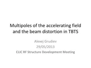
This presentation by Alexej Grudiev focuses on the multipole expansion of the accelerating field in the TBTS (Test Beamline for the CLIC) and its impact on beam distortion. It discusses the electric field multipole expansion, particularly looking at the skew components and the Panofsky-Wenzel theorem. The impacts of RF kicks on the beam dynamics are examined, with a specific emphasis on octupolar components. Comparisons between Lorentz force and Panofsky-Wenzel kick strengths reveal distinct behaviors that influence beam stability, particularly during multi-bunch operations.

E N D
Multipoles of the accelerating field and the beam distortion in TBTS Alexej Grudiev 29/05/2013 CLIC RF Structure Development Meeting
Mesh TD24_vg1p8 Ntetr = 1188991; dxyz ~ 0.5 mm near axis
Multipole expansion of Ez Accelerating gradient: Accelerating voltage: Multipole expansion in vacuum only: Skew components = 0 due to the symmetry Panofsky-Wenzel (PW) theorem: Gives an expression for multipolar RF kicks: Lorenz Force (LF): Gives an expression for kick directly from the RF EM fields: Which can be decomposed into multipoles: Equating the RF and magnetic kicks, RF kick strength can be expressed in magnetic units:
TD24_vg1p8: quadrupolar kick; LF versus PW Comparison b(2) @Vz=1V LF: 0.10 - 0.91i [nTm/m2] PW: 0.02 - 0.65i [nTm/m2] • Quadrupolar kick strength Fx and corresponding multipole of Eacc(2) have very different dependence along the beam axis but the integrals are equal.
TD24_vg1p8: octupolar kick; LF versus PW Octupolar kick is maximum for particle on zero crossing. Comparison b(4) @Vx=1V LF: 0.17 +3.23i [mTm/m2] PW: 0.22 +3.22i [mTm/m2]
Summary table for Vz = 22.8 MV; Pin = 46.5 MW NB: the b(n)‘s B-field : By(n)(y=0,x=x0) = b(n)x0n-1. This is not MAD convention for multipolar strength. There is the following dependences of the multipolar kick on the RF phase, where δφs is the deviation of the (macro)particle RF phase from the crest
Beam spot distortion due to Octupole Beam spot: in the structure on the screen Wilfred Farabolini
Beam spot distortion due to Octupole Beam spot: in the structure on the screen Wilfred Farabolini
Beam spot distortion due to Octupole Beam spot: in the structure on the screen
Beam spot distortion due to Octupole Beam spot: in the structure on the screen
Beam spot distortion due to Octupole Beam spot: in the structure on the screen
Beam spot distortion due to Octupole Beam spot: in the structure on the screen
Beam spot distortion due to Octupole Beam spot: in the structure on the screen
Beam spot distortion due to Octupole Beam spot: in the structure on the screen
Beam spot distortion due to Octupole Beam spot: in the structure on the screen
Beam spot distortion due to Octupole Beam spot: in the structure on the screen
Beam spot distortion due to Octupole Beam spot: in the structure on the screen
Beam spot distortion due to Octupole Beam spot: in the structure on the screen Wilfred Farabolini
Thanks for your attention • Probe beam distortion in TBTS is due to octupolar component of the 12 GHz accelerating field • RF octupole is 90 degree out of phase with respect to the accelerating field. Maximum octupolar kick at 0-crossing of the main RF • 8-star shape of the beam near the on crest acceleration (0-crossing for RF octupole) is probably due to multi-bunch RF phase spread