Download
1 / 54
540 likes | 739 Views
A Fourier Series Kicker for the TESLA Damping Rings. George Gollin Department of Physics University of Illinois at Urbana-Champaign LCRD 2.22. Introduction. The TESLA damping ring fast kicker must inject/eject every n th bunch, leaving adjacent bunches undisturbed.

E N D
A Fourier Series Kicker for the TESLA Damping Rings George Gollin Department of Physics University of Illinois at Urbana-Champaign LCRD 2.22 George Gollin, Cornell LC 7/03
Introduction • The TESLA damping ring fast kicker must inject/eject every nth bunch, leaving adjacent bunches undisturbed. • The minimum bunch separation inside the damping rings (which determines the size of the damping rings) is limited by the kicker design. • We are investigating a novel extraction technique which might permit smaller bunch spacing: a “Fourier series kicker” in which a series of rf kicking cavities is used to build up the Fourier representation of a periodic d function. • Various issues such as finite bunch size, cavity geometry, and tune-related effects are under investigation. George Gollin, Cornell LC 7/03
Outline • Overview • TESLA damping rings and kickers • how a “Fourier series kicker” might work • Phasor representation of pT and dpT/dt • Flattening the kicker’s dpT/dt • Some of the other points: • finite separation of the kicker elements • timing errors at injection/extraction • Conclusions George Gollin, Cornell LC 7/03
Illinois participants in LCRD 2.22 Guy Bresler (REU student, from Princeton) Keri Dixon (senior thesis student, from UIUC) George Gollin (professor) Mike Haney (engineer, runs HEP electronics group) Tom Junk (professor) We benefit from good advice from people at Fermilab and Cornell. In particular: Dave Finley, Vladimir Shiltsev, Gerry Dugan, and Joe Rogers.
Overview: linac and damping ring beams • Linac beam (TESLA TDR): • One pulse: 2820 bunches, 337 nsec spacing (five pulses/second) • length of one pulse in linac ~300 kilometers • Cool an entire pulse in the damping rings before linac injection • Damping ring beam (TESLA TDR): • One pulse: 2820 bunches, ~20 nsec spacing • length of one pulse in damping ring ~17 kilometers • Eject every nth bunch into linac (leave adjacent bunches undisturbed) • 17 km damping ring circumference is set by the minimum bunch spacing in the damping ring: Kicker speed is the limiting factor. George Gollin, Cornell LC 7/03
Fast kicker specs (à la TDR): • Bdl = 100 Gauss-meter = 3 MeV/c • stability/ripple/precision ~.07 Gauss-meter = 0.07% • ability to generate, then quench a magnetic field rapidly determines the minimum achievable bunch spacing in the damping ring Overview: TESLA TDR fast kicker TDR design: bunch “collides” with electromagnetic pulses traveling in the opposite direction inside a series of traveling wave structures. TDR Kicker element length ~50 cm; impulse ~ 3 Gauss-meter. (Need 20-40 elements.) Structures dump each electromagnetic pulse into a load. George Gollin, Cornell LC 7/03
Something new: a “Fourier series kicker” Fourier series kicker would be located in a bypass section. While damping, beam follows the dog bone-shaped path (solid line). During injection/extraction, deflectors route beam through bypass (straight) section. Bunches are kicked onto/off orbit by kicker. George Gollin, Cornell LC 7/03
Fourier series kicker Kicker would be a series of N “rf cavities” oscillating at harmonics of the linac bunch frequency 1/(337 nsec) = 2.97 MHz: George Gollin, Cornell LC 7/03
Fourier series kicker Run them at 3 MHz, 6 MHz, 9 MHz,… (original idea) or perhaps at higher frequencies, with 3 MHz separation: fhigh, fhigh+3 MHz, fhigh+6MHz,... (Shiltsev’s suggestion) Cavities oscillate in phase, possibly with equal amplitudes. They are always on so fast filling/draining is not an issue. Kick could be transverse, or longitudinal, followed by a dispersive (bend) section (Dugan’s idea). High-Q: perhaps amplitude and phase stability aren’t too hard to manage? George Gollin, Cornell LC 7/03
(actually, one would want to use more than ten cavities) A ten-cavity system might look like this (fhigh = 300 MHz): Kicker pT George Gollin, Cornell LC 7/03
1 2 3 4 5 6 7 8 9 10 Kicked bunches are here… Bunch timing …undisturbed bunches are here (call these “major zeroes”) Interval between kick and adjacent “major zeroes” is uniform.
Extraction cycle timing Assume bunch train contains a gap between last and first bunch while orbiting inside the damping ring. 1. First deflecting magnet is energized. George Gollin, Cornell LC 7/03
Extraction cycle timing 2. Second deflecting magnet is energized; bunches 1, N+1, 2N+1,… are extracted during first orbit through the bypass. George Gollin, Cornell LC 7/03
Extraction cycle timing 3. Bunches 2, N+2, 2N+2,… are extracted during second orbit through the bypass. 4. Bunches 3, N+3, 2N+3,… are extracted during third orbit through the bypass. 5. Etc. (entire beam is extracted in N orbits) George Gollin, Cornell LC 7/03
Just run the movie backwards… Injection cycle timing With a second set of cavities, it should work to extract and inject simultaneously. George Gollin, Cornell LC 7/03
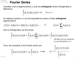
Here are some plots for a kicker system using frequencies 300 MHz, 303 MHz, 306 MHz,… and equal amplitudes Aj : Define Sometimes pT can be summed analytically… George Gollin, Cornell LC 7/03
Represent each cavity’s kick as a “phasor” (vector) whose x component is the kick, and whose y component is not... Lots of algebra. Visualizing this… Each cavity’s phasor spins around counterclockwise…
The horizontal component of the phasor (vector) sum indicates pT. Here’s a four-phasor sum as an example: Phasors: visualizing the pT kick George Gollin, Cornell LC 7/03
pT start here end here Here’s a 10-cavity phasor diagram for equal-amplitude cavities… Phasors: visualizing the pT kick …and 30-cavity animations (30, A, B, C).
…are zero when (m is integral) Both the xandy components of the phasor sum… Phasors: visualizing the pT kick
Kicks occur when the denominator is zero: “Major zeroes” between two kicks are evenly spaced and occur at Phasors: visualizing the pT kick One kicker cycle comprises a kick followed by (Ncavities - 1) major zeroes. George Gollin, Cornell LC 7/03
Phasors when pT = 0 (30 cavities) • Phasor diagrams for major zeroes of one specific example: • 30 cavity system • 300 MHz lowest frequency, 3 MHz spacing green dot: tip of first phasor larger red dot: tip of last phasor zero #1 zero #2
Phasors when pT = 0 (30 cavities) zero #3 zero #4 George Gollin, Cornell LC 7/03
Phasors when pT = 0 (30 cavities) zero #5 zero #6 George Gollin, Cornell LC 7/03
Phasors when pT = 0 (30 cavities) zero #7 zero #8 George Gollin, Cornell LC 7/03
Phasors when pT = 0 (30 cavities) zero #9 zero #10 George Gollin, Cornell LC 7/03
Phasors when pT = 0 (30 cavities) zero #11 zero #12 George Gollin, Cornell LC 7/03
Phasors when pT = 0 (30 cavities) zero #13 zero #14 George Gollin, Cornell LC 7/03
Phasors when pT = 0 (30 cavities) zero #15 zero #16 George Gollin, Cornell LC 7/03
Phasors when pT = 0 (30 cavities) zero #17 zero #18 …and so forth. (There are 29 major zeroes in all.) George Gollin, Cornell LC 7/03
We’d like the slopes of the pT curves when not-to-be-kicked bunches pass through the kicker to be as small as possible so that the head, center, and tail of a (20 ps rms) bunch will experience about the same field integral. dpT/dt considerations 1% of kick 1 nsec pT in the vicinity of two zeroes
Sometimes dpT/dt at zeroes can be calculated… At the mth “major zero” the expression evaluates to Note that magnitude of the slope does not depend strongly on whigh. (It does for the other zeroes, however.)
pT = 0 Flattening out dpT/dt Endpoint is moving this way at the zero in pT (80 psec intervals) George Gollin, Cornell LC 7/03
Flattening out dpT/dt In terms of phasor sums: we want the endpoint of the phasor sum to have as small an x component of “velocity” as possible. Endpoint velocity components (m ranges from 1 to Ncavities – 1): George Gollin, Cornell LC 7/03
Flattening out dpT/dt • How large a value for vx is acceptable? • Size of kick: Ncavities • rms bunch length: 20 psec (6 mm) • maximum allowable kick error: ~.07% Work in units of nsec and GHz… for 30 cavities: vx < 1.05 nsec-1. George Gollin, Cornell LC 7/03
Phasor magnitude for mth zero’s dpT/dt: ~maximum allowable value Phasor plots for dpT/dt Phasor angle:
1 29 4 3 28 2 Phasor plot for dpT/dt, including the phasor angles… Phasor plots for dpT/dt Ncavities = 30 K=100 (300MHz, 3 MHz) Between the blue lines is good. There are lots of parameters to play with.
Ncavities = 30, K=99 Ncavities = 30, K=101 Ncavities = 30, K=100 Ncavities = 31, K=100 Ncavities = 29, K=100 Changing parameters
More dramatic dpT/dt reduction… …is possible with different amplitudes Aj in each of the cavities. We (in particular Guy Bresler) are investigating this right now. It looks very promising! Guy has constructed an algorithm to find sets of amplitudes which have dpT/dt = 0 at evenly-spaced “major zeroes” in pT. There are lots of different possible sets of amplitudes which will work. George Gollin, Cornell LC 7/03
Here’s one set for a 29-cavity system (which makes 28 zeroes in pT and dpT/dt in between kicks), with 300 MHz, 303 MHz,…: More dramatic dpT/dt reduction… George Gollin, Cornell LC 7/03
Kick corresponding to those amplitudes The “major zeroes” aren’t quite at the obvious symmetry points. George Gollin, Cornell LC 7/03
Kick corresponding to those phasors Here’s where some of them are. George Gollin, Cornell LC 7/03
Phasors with amplitudes chosen to give dpT/dt = 0 andpT = 0 (29 cavities) zero #1 zero #2 The phasor sums show less geometrical symmetry. George Gollin, Cornell LC 7/03
Phasors with amplitudes chosen to give dpT/dt = 0 andpT = 0 (29 cavities) zero #3 zero #4 etc. George Gollin, Cornell LC 7/03
Old, equal-amplitudes scheme: ~maximum allowable value New, intelligently-selected-amplitudes scheme: ~maximum allowable value How well do we do with these amplitudes? bunch number Wow! bunch number
Multiple passes through the kicker • Previous plots were for a single pass through the kicker. • Most bunches make multiple passes through the kicker. • Modeling of effects associated with multiple passes must take into account damping ring’s • synchrotron tune (0.10 in TESLA TDR) • horizontal tune (72.28 in TESLA TDR) • We (in particular, Keri Dixon) are working on this now. • With equal-amplitude cavities some sort of compensating gizmo on the injection/extraction line (or immediately after the kicker) is probably necessary. However… George Gollin, Cornell LC 7/03
maximum allowed value bunch number …selecting amplitudes to zero out pT slopes fixes the problem! Here’s a worst-case plot for 300 MHz,… (assumes tune effects always work against us). Multiple passes through the kicker
Some of our other concerns • Effect of finite separation of the kicker cavities along the beam direction (George) • Arrival time error at the kicker for a bunch that is being injected or extracted (Keri) • Inhomogeneities in field integrals for real cavities (Keri) • What is the optimal choice of cavity frequencies and amplitudes? (Guy) George Gollin, Cornell LC 7/03
Finite separation of the kicker cavities Even though net pT is zero there can be a small displacement away from the centerline by the end of an N-element kicker. For N = 16; 50 cm cavity spacing; 6.5 Gauss-meter per cavity: Non-kicked bunches only (1, 2, 4, … 32) George Gollin, Cornell LC 7/03
Non-kicked bunches only (N = 1, 2, 4, … 32) Finite separation of the kicker cavities Compensating for this: insert a second set of cavities in phase with the first set, but with the order of oscillation frequencies reversed: 3 MHz, 6 MHz, 9MHz,… followed by …, 9 MHz, 6 MHz, 3 MHz. George Gollin, Cornell LC 7/03