Download
1 / 18
180 likes | 270 Views
Lecture Objectives:. Finish wit introduction of HVAC Systems Introduce major ES software. Building. Heating/Cooling System. Plant. Integration of HVAC and building physics models. Load System Plant model. Building. Q buiolding. Heating/Cooling System. Q including

E N D
Lecture Objectives: • Finish wit introduction of HVAC Systems • Introduce major ES software
Building Heating/Cooling System Plant Integration of HVAC and building physics models Load System Plant model Building Qbuiolding Heating/Cooling System Q including Ventilation and Dehumidification Plant Integrated models
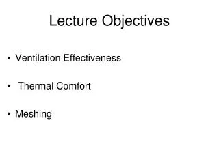
Example of System Models:Schematic of simple air handling unit (AHU) Mixing box m - mass flow rate [kg/s], T – temperature [C], w [kgmoist/kgdry air], r - recirculation rate [-], Q energy/time [W]
Energy and mass balance equations for Air handling unit model – steady state case The energy balance for the room is given as: mS is the supply air mass flow rate cp- specific capacity for air, TRis the room temperature, TS is the supply air temperature. The air-humidity balance for room is given as: wRand wS are room and supply humidity ratio - energy for phase change of water into vapor The energy balance for the mixing box is: ‘r’ is the re-circulated air portion, TO is the outdoor air temperature, TM is the temperature of the air after the mixing box. The air-humidity balance for the mixing box is: wOis the outdoor air humidity ratio and wM is the humidity ratio after the mixing box The energy balance for the heating coil is given as: The energy balance for the cooling coil is given as:
Non-air system Radiant panel heat transfer model The total cooling/heating load in the room The energy extracted/added by air system The energy extracted/added by the radiant panel: The energy extracted/added by the radiant panel is the sum of the radiative and convective parts: The radiant panel energy is:
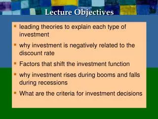
Example of Plant Models:Chiller P electric () = COP () x Q cooling coil () TOA What is COP for this air cooled chiller ? T Condensation = TOA+ ΔT Evaporation at 1oC TCWS=5oC TCWR=11oC water Building users (cooling coil in AHU) COP is changing with the change of TOA
Chiller model: COP= f(TOA , Qcooling , chiller properties) Chiller data: QNOMINAL nominal cooling power, PNOMINAL electric consumption forQNOMINAL The consumed electric power [KW] under any condition Available capacity as function of evaporator and condenser temperature Cooling water supply Outdoor air Full load efficiency as function of condenser and evaporator temperature Efficiency as function of percentage of load Percentage of load: The coefficient of performance under any condition:
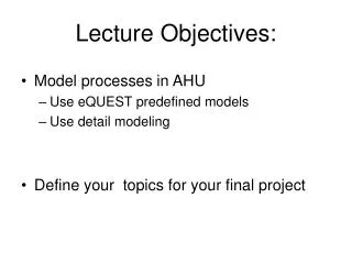
ASCI file ASCI file Structure of ES programs Graphical User Interface (GUI) Solver Interface for input data Interface for result presentation Preprocessor Preprocessor Engine
Preprocessor Solver Postprocessor ES program Modeling steps • Define the domain • Analyze the most important phenomena and define the most important elements • Discretize the elements and define the connection • Write energy and mass balance equations • Solve the equations • Present the result
Characteristic parameters • Conduction (and accumulation) solution method • finite dif (explicit, implicit), response functions • Time steps • Meteorological data • Radiation and convection models (extern. & intern.) • Windows and shading • Infiltration models • Conduction to the ground • HVAC and control models
ES programs • Large variety • http://www.eere.energy.gov/buildings/tools_directory • DOE2 • eQUEST (DOE2) • BLAST • ESPr • TRNSYS • EnergyPlus (DOE2 & BLAST)
eQUEST (DOE2)US Department of Energy & California utility customers • eQUEST - interface for the DOE-2 solver • DOE-2 - one of the most widely used ES program - recognized as the industry standard • eQUEST very user friendly interface • Good for life-cycle cost and parametric analyses • Not very large capabilities for modeling of different HVAC systems • Many simplified models • Certain limitations related to research application - no capabilities for detailed modeling
ESPrUniversity of Strathclyde - Glasgow, Scotland, UK • Detailed models – Research program • Use finite difference method for conduction • Simulate actual physical systems • Enable integrated performance assessments Includes daylight utilization, natural ventilation, airflow modeling CFD, various HVAC and control models • Detail model – require highly educated users • Primarily for use with UNIX operating systems
TRNSYSSolar Energy Lab - University of Wisconsin • Modular system approach • One of the most flexible tools available • A library of components • Various building models including HVAC • Specialized for renewable energy and emerging technologies • User must provide detailed information about the building and systems • Not free
EnergyPlusU S Department of Energy • Newest generation building energy simulation program ( BLAST + DOE-2) • Accurate and detailed • Complex modeling capabilities • Large variety of HVAC models • Some integration wit the airflow programs Zonal models and CFD • Detail model – require highly educated users • Very modest interface • Third party interface – very costly