Download
1 / 9
100 likes | 142 Views
Explore the principles of confocal microscopy, including Snell’s law for total internal reflection, usage of oil immersion objectives, pixel sampling, and z-resolution optimization. Learn about scan rates, photon flux, Nyquist criterion, and z-correction factors.

E N D
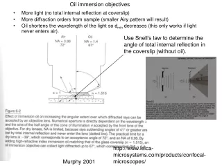
Use Snell’s law to determine the angle of total internal reflection in the coverslip (without oil). Oil immersion objectives • More light (no total internal reflection at coverslip) • More diffraction orders from sample (smaller Airy pattern will result) • Oil shortens the wavelength of the light so dmin decreases (this only works if light never enters air). http://www.leica-microsystems.com/products/confocal-microscopes/ Murphy 2001
500 um Adapted from Pawley 2004 dmin=1.22 λ / 2NA In terms of fundamentals of optics, for 2 points to be resolved, the max. of one object’s diffraction pattern must overlap the 1st min. of the other. This is called the Raleigh/Abbe criterion. This 500um scan range can be mapped to ??? pixels. The scan itself can be other than 1:1 aspect ratio but the pixels are each 1:1. These represent light from the object as it is focused at the image plane. They are not points! ~1 micron (for a good oil objective) ~1 micron (for a good oil objective) undersampled properly sampled When sampling with more pixels, adjust scan rate to increase photons/pixel; this is a good idea unless you are worried about beam damage! The top row of 3 scans (not in box) was done at constant scan rate (what is the scan rate for the top row?) The photon flux from the sample in all cases is 16 photons/second. fast (? sec/scan) slow (4 sec/scan) Slowest (? sec/scan) In terms of instrumental sampling, we want 2 pixels to fit in the linear dimension of each pattern (4 pixels/area). Here we are matching our optical resolution to our instrumental resolution. This is called the Nyquist criterion. How can oversampling be a problem? Assuming the 1 micron dimension is correct, what is the size of each pixel? What do we mean by sampling? The Bio-Rad MRC1024 (when not set to low signal) automatically corrects for changes in scan rate by decreasing PMT (photomultiplier tube) output at slower scan rates. With low signal turned on, collect images at slow and normal scan rates (what are these rates in lines/sec)? How does this value relate to temporal (time) resolution?
Axial or z resolution: zmin= 2 λair ηsample / (NAobj)2 DON’T MEMORIZE When doing 3D confocal microscopy, we want to match our corrected z-step with the proper sampling depth of our setup. It also helps some reconstruction programs if we can make our xy:z aspect ratio an interger value. z y y or x x University of Helsinki This is ultimate z resolution, how does our z resolution change with confocal iris size? Adjust scan size, z step, scan rate, and pixel count to match your objective lens and sample. Now, image the same sample with each of the above parameters set to non-optimal settings.
During z-series acquisition the distance in z axis travel by the objective or sample is different than the change in z of the focal plane. The next 3 slides show why it is necessary to use a z-correction factor when collecting stacks of optical sections (z-series).
20X NA .71 160 / .17 When you turn the focus knob and move the objective 10um closer to the sample what is the change in plane of focus in the sample? Extreme ray angle (degrees) 45 air, 28 glass, 32 water 20X NA .71 160/.17 microscope tube length coverslip thickness, 170um α 1 Often, the WD printed on the objective actually is a measure of the distance between the objective front lens and the coverslip. 170 um given WD air α 1 190 um given (you can start at any focal distance you want to, just turn the focus knob) α 2 WD water with coverslip 90um 119um
Extreme ray angle (degrees) 45 air, 28 glass, 32 water 20X NA .71 160/.17 We use peripheral rays for correction factor. (Visser & N.S. White use modal rays, see ref. at end) 10um 10um 170 um α 1 α 2 206 um (now we’ve moved the focus knob (objective) 10 microns closer to our sample) 90um 129 um
Gaussian z depth correction factor for z series reconstruction • NA = (refractive index of medium at lens) η x sin α • Nominal z-step = 10 um • Actual z-step = 16um • Nominal z-step/correction factor = optical z-step • Correction factor = .63 (also .63 when simple equation used: η1 x cosα1 / η2 x cosα2 ) • Coversilp determines absolute focal depth but has no effect on focal shift with change in focal depth because its thickness is constant while the depth into sample is not. As described in Zill, 2000. Microscopy Research and Technique Volume 48 Issue 6, Pages 367 - 384. Based on work of Nick White and Stefan Hell from early 1990s.
Be aware of spectral bleed through or leakage; picking up the same emissions in 2 or more channels. This can appear to be co-localization when it is not. Interestingly, these diagramatic grey filter bands shown here are much more like the leica SP5 slits in shape than the older interference filters they are meant to represent in these spectra (interference filters do not have quite as sharp cut on/off characteristics). invitrogen.molecular.spectra.viewer