Download
1 / 15
150 likes | 173 Views
Explore the latest advancements in detector suspension system upgrades for improved vibration control in the scientific sphere. Discover innovations in the Superattenuator, IP legs, and PIEZO actuator integration.

E N D
The Superattenuator upgrades and the SAFE Project F. Frasconi – INFN Pisa (ET- General Workshop – Erice – October 14-16, 2009)
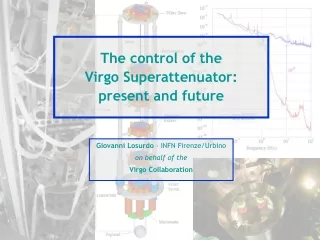
The VIRGO Suspension System • The passive attenuation performance of the present Superattenuator (SA) is compliant with next generation detectors • Even if all inner mechanical modes have been confined in the low frequency range, a few upgrades are possible improving the performance of the feedback control. F. Frasconi - INFN Pisa
IP legs F0 Crossbar The IP inner modes • The VIRGO commissioning put in evidence two minor problems: - the first flexural mode of IP legs - the inner modes of F0 crossbar structure F. Frasconi - INFN Pisa
The SAFE project & the New IP • The SAFE project is based on a revision of the IP mechanical structure devoted to improve the ID control performance; • IP mechanical structure: - leg flexural resonance around 10 Hz limits the control band; - improving the rigidity of the top stage will reduce the frequency bump around 15 Hz; - installation of PIEZO actuators for vertical control improvement and tilt control. F. Frasconi - INFN Pisa
The monolithic IP leg • The new IP design has been conceived with: • Aluminum monolithic legs; • increased sectional area (higher momentum of inertia - 160 mm outer diameter and 150 mm inner diameter); • using the same elastic element (Maraging flex joint) • with these improvements the leg flexural frequency will be around 20 Hz. F. Frasconi - INFN Pisa
Old IP & New IP • - F0 replaced with a rigid platform: Disk Zero • - IP legs replaced with monolithic ones • room available within the feet for PIEZO accommodation. F. Frasconi - INFN Pisa
SAFE: the New IP Main features: • Short Al monolithic legs (4280 mm instead of 5340 mm); • More rigid structure; • Same elastic element (Maraging flex joint); • Same tunable counterweight for a precise percussion point positioning; • Available room within feet for PIEZO actuator accommodation. F. Frasconi - INFN Pisa
The Disk Zero • A more rigid top stage replacing the F0 has been designed as new inertial platform; • Inner modes at higher frequencies; • A detailed FEA has been done (A. Basti, F. Frasconi). F. Frasconi - INFN Pisa
The PIEZO actuators • Since the beginning the IP mechanical structure was conceived with the possibility to install three PIEZO actuators within the feet structure; • The IP was designed to be controllable in all six degree of freedom (including the tilt control): the PIEZO actuator acts against the elastic element mounted on each IP foot. F. Frasconi - INFN Pisa
PIEZO Accommodation L V D T Acc. BottomRing PIEZO calibration measurements • A measurements set-up for PIEZO characterization has been prepared. Three displacement sensors (LVDT) and three actuators have been installed within the IP feet. F. Frasconi - INFN Pisa
PIEZO calibration measurements (cont.) • The LVDT sensors have been used to monitor the PIEZO actuators response (as function of the applied load and working conditions) on the SAFE facility. F. Frasconi - INFN Pisa
The SAFE set-up • Maintaining the distance between the Payload and the last mechanical filter equal to that one of the VIRGO setting up, the SAFE system will have identical distance between two consecutive filters along the suspension chain F. Frasconi - INFN Pisa
Activities in progress • A movable scaffolding structure surrounding SAFE has been built and installed; • The new IP prototype has been installed within the vacuum tank; • The PIEZO actuators and their driver electronic have been characterized; • The leak test of the first part of the vacuum tank has been done reaching a vacuum level of 4*10-5 mbar; • The construction of the new top stage (Disk Zero) is in progress; • A new set-up for preliminary feedback control test with horizontal accelerometer on IP bottom ring is in preparation; • A common (with MS activity test – E. Majorana) DAQ chain has been installed for next experimental activities. F. Frasconi - INFN Pisa
Preliminary M. Passuello Simulation in progress • A preliminary model of the SA for simulation purpose has been developed (A. Gennai, M. Passuello); • An optimization of the chain parameters (pendulum length, masses, etc.) is in progress considering the ET requirements and the possibility to extend the detection band in the low frequency region. [see: A. Bove et al., Europhys. Lett., 40 (6), pp. 601-606, (1997) G. Cella et al., “Mitigating noise in future GW observatories in the 1-10 Hz band”, (2009)] F. Frasconi - INFN Pisa
Final Considerations • Some improvements have been introduced in the new IP mechanical structure to overcome the ID control band limit; • The three PIEZO will be used to improve the vertical ID performance and they represent also actuation points to compensate the ground tilt motion (hopefully having a suited tilt sensor); • The simulation study for a suspension system of the ET Project is oriented to the parameters optimization (pendulum length, masses, etc.) maintaining the total length as close as possible to the present one; • The SAFE facility should be considered a test bench for next generation detectors. F. Frasconi - INFN Pisa