Download
1 / 1
10 likes | 106 Views
Designing ultra-narrowband interference filters. Sonia Cianci a,b , Joss Bland-Hawthorn b and John O’Byrne a a University of Sydney, Australia b Anglo-Australian Observatory. DAZLE FILTER DESIGN.

E N D
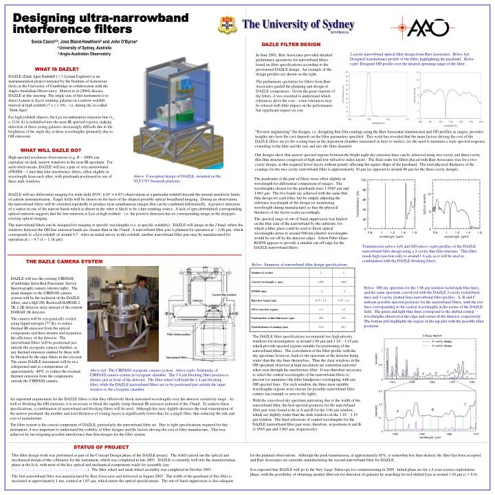
Designing ultra-narrowband interference filters Sonia Ciancia,b, Joss Bland-Hawthornb and John O’Byrnea a University of Sydney, Australia b Anglo-Australian Observatory DAZLE FILTER DESIGN 2-cavity narrowband optical filter design from Barr Associates. Below left: Designed transmittance profile of the filter, highlighting the passband. Belowright: Designed OD profile over the desired operating range of the filter. In June 2001, Barr Associates provided detailed preliminary quotations for narrowband filters based on filter specifications according to the provisional DAZLE design. An example of the design profiles are shown on the right. The preliminary quotation for filters from Barr Associates guided the planning and design of DAZLE components. Given the great expense of the filters, it was essential to understand which tolerances drive the cost – some tolerances may be relaxed with little impact on the performance but significant impact on cost. WHAT IS DAZLE? DAZLE(Dark Ages Redshift (‘z’) Lyman Explorer) is an instrumentation project initiated by the Institute of Astronomy (IoA) at the University of Cambridge in collaboration with the Anglo-Australian Observatory. Horton et al (2004) discuss DAZLE at this meeting. The single aim of this instrument is to detect Lyman- (Ly) emitting galaxies in a narrow redshift interval at high redshift (7 < z < 10) – i.e. during the so-called ‘Dark Ages’. For high-redshift objects, the Lyα recombination emission line (o = 1216 Å) is redshifted into the near-IR spectral regions, making detection of these young galaxies increasingly difficult due to the brightness of the night sky at these wavelengths (primarily due to OH emission). “Reverse engineering” the designs, i.e. designing thin film coatings using the Barr Associates transmission and OD profiles as targets, provides insights into how the cost depends on the filter parameters specified. This work has revealed that the main factors driving the cost of the DAZLE filters are (i) the coating time in the deposition chamber (measured in days to weeks), (ii) the need to maintain a wide spectral response extending to the blue and the red, and (iii) the filter diameter. WHAT WILL DAZLE DO? Our designs show that narrow spectral regions between the bright night sky emission lines can be achieved using two-cavity and three-cavity thin film structures composed of high and low refractive index layers. The final order for filters placed with Barr Associates was for a two-cavity design, as this required fewer layers without greatly affecting the square shape of the passband. The total physical thickness of the coatings for the two-cavity narrowband filter is approximately 30 m (as opposed to around 40 m for the three-cavity design). High spectral resolution observations (e.g. R ~ 1000) can capitalize on dark, narrow windows in the near-IR spectrum. For such observations, DAZLE will use a pair of very narrowband (FWHM ~ 1 nm) thin film interference filters, offset slightly in wavelength from each other, with passbands positioned in one of these dark windows. Above: Conceptual design of DAZLE, mounted on the VLT UT3 Nasmyth platform. The passbands of the pair of filters were offset slightly in wavelength for differential comparison of images. The wavelengths chosen for the passbands were 1.0565 m and 1.063 m. The two bands are achieved with the same thin film design for each filter, but by simply adjusting the reference wavelength of the design (or monitoring wavelength during manufacture) so that the physical thickness of the layers scales accordingly. The spectral range of out-of-band suppression was limited on the blue side of the narrowband by the substrate, for which a filter glass could be used to block optical wavelengths down to around 500 nm (shorter wavelengths would be cut off by the detector edge). Schott Filter Glass RG850 appears to provide a suitable cut-off edge for the DAZLE narrowband filters. DAZLE will use differential imaging for wide-field (FOV: 6.83′ × 6.83′) observations at a particular redshift beyond the normal sensitivity limits of current instrumentation. Target fields will be chosen on the basis of the deepest possible optical broadband imaging. During an observation, the narrowband filters will be switched repeatedly to produce near-simultaneous images that can be combined differentially. A positive detection of a source in one of the narrow bands which is absent in the other is likely to be a line-emitting source. A lack of (pre-determined) corresponding optical emission suggests that the line emission is Ly at high redshift – i.e. the positive detection has no corresponding image in the deep pre-existing optical imaging. The narrowband filters can be designed for imaging at specific wavelengths (i.e. at specific redshifts). DAZLE will image in the J band, where the windows between the OH line emission bands are cleaner than in the I band. A narrowband filter pair is planned for operation at ~ 1.06 m, which corresponds to a Ly redshift of around 8.7. After an initial survey at this redshift, another narrowband filter pair may be manufactured for operation at z ~ 9.7 ( ~ 1.18 m). Transmission (above left) and OD (above right) profiles of the DAZLE narrowband filter design using a 2-cavity thin film structure. This filter needs high rejection only to around 1.4 m, as it will be used in combination with the DAZLE blocking filters. THE DAZLE CAMERA SYSTEM Below: Summary of narrowband filter design specifications. DAZLE will use the existing CIRPASS (Cambridge Infra-Red Panoramic Survey Spectrograph) camera (shown right). The main changes to the CIRPASS camera system will be the inclusion of the DAZLE filters, and a HgCdTe Rockwell HAWAII-2 2K x 2K detector array instead of the current HAWAII 1K detector. The camera will be cryogenically cooled using liquid nitrogen (77 K), to reduce thermal IR emission from the optical components and their mounts and maximize the efficiency of the detector. The narrowband filters will be positioned just outside the cryogenic camera chamber, as any thermal emission emitted by these will be blocked by the edge filters in the cryostat. The entire DAZLE instrument will be in a refrigerated unit at a temperature of approximately -40ºC, to reduce the residual thermal emission from the components outside the CIRPASS camera. Below: OH sky spectrum for the 1.06 m window (solid dark blue line), and the same spectrum convolved with the DAZLE 2-cavity (solid black line) and 3-cavity (dotted line) narrowband filter profiles. A, B and C indicate possible spectral positions for the narrowband filters, with the red lines corresponding to the central wavelengths at the centre of the DAZLE field. The green and light blue lines correspond to the shifted central wavelengths observed at the edge and corner of the detector, respectively. The bottom plot highlights the region of the top plot with the possible filter positions. The DAZLE filter specifications recommend two high priority windows for investigation, at around 1.06 m and 1.18 – 1.19 m, which provide spectral regions suitable for positioning of the narrowband filters. The convolution of the filter profile with the sky spectrum, however, leads to the spectrum at the detector being wider than the sky lines themselves. Thus the clear windows in the OH spectrum observed at high resolution are somewhat narrower when seen through the interference filter. It was therefore necessary to select the central wavelengths of the narrowband filters to prevent (or minimise) the filter bandpasses overlapping with any OH spectral lines. For each window, the three most suitable wavelengths regions were chosen for possible narrowband filter centres (an example is seen to the right). With the convolved sky spectrum narrowing due to the width of the narrowband filter, the best spectral positions for the narrowband filter pair were found to be at A and B for the 1.06 m window, which are slightly wider than the dark windows in the 1.18 – 1.19 m window. The final selections of central wavelengths for the DAZLE narrowband filter pair were, therefore, at positions A and B (1.0565 m and 1.063 m, respectively). Above left: The CIRPASS cryogenic camera system. Above right: Schematic of CIRPASS camera system in cryogenic chamber. The 1.8 μm blocking filter position is shown, just in front of the detector. The filter wheel will hold the 1.4 μm blocking filter, while the DAZLE narrowband filters are to be positioned just outside the input window to the cryogenic chamber. An important requirement for the DAZLE filters is that they effectively block unwanted wavelengths over the detector sensitivity range. As well as blocking the OH emission, it is necessary to block the rapidly rising thermal IR emission redward of the J band. To achieve these specifications, a combination of narrowband and blocking filters will be used. Although this may slightly decrease the total transmission of the narrow passband, the number and total thickness of coating layers is significantly lower than for a single filter, thus reducing the risk and cost of manufacture. The filter system is the crucial component of DAZLE, particularly the narrowband filter set. Due to tight specifications required for this instrument, it was important to understand the viability of filter designs and the factors driving the cost of filter manufacture. This was achieved by investigating possible interference thin film designs for the filter system. STATUS OF PROJECT This filter design work was performed as part of the Concept Design phase of the DAZLE project. The AAO carried out the optical and mechanical design of the collimator for the instrument, which was completed in late 2003. DAZLE is currently well into the manufacturing phase at the IoA, with most of the key optical and mechanical components ready for assembly (see http://www.ast.cam.ac.uk/~optics/dazle/photos/). The filter wheel and mask wheel assembly was completed in October 2003. The first narrowband filter was manufactured by Barr Associates and delivered in August 2003. The width of the passband of this filter is measured at approximately 1 nm, centred at 1.05 m, which meets the optical specifications. The out-of-band suppression is also adequate for the planned observations. Although the peak transmission, at approximately 65%, is somewhat less than desired, the filter has been accepted, and Barr Associates are currently manufacturing the second narrowband filter for DAZLE. It is expected that DAZLE will go to the Very Large Telescope for commissioning in 2005. Initial plans are for a 4-year science exploitation phase, with the possibility of obtaining another filter set for detection of galaxies by searching for red-shifted Ly at around 1.18 m (z = 8.8).