Download
1 / 1
10 likes | 114 Views
Computational Modeling and Analysis of Radar Scattering by Metallic Body-Worn Explosive Devices Covered with Wrinkled Clothing. Amanda J. Angell and Carey M. Rappaport Contact: angell.a@neu.edu.

E N D
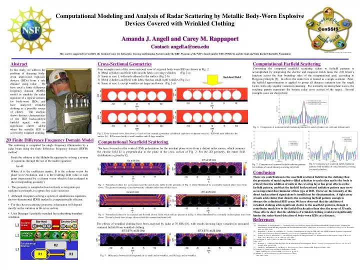
Computational Modeling and Analysis of Radar Scattering by Metallic Body-Worn Explosive Devices Covered with Wrinkled Clothing Amanda J. Angell and Carey M. Rappaport Contact: angell.a@neu.edu This work is supported by CenSSIS, the Gordon Center for Subsurface Sensing and Imaging Systems under the ERC Program of the NSF (Award number EEC-9986821), and the Saul and Gitta Kurlat Charitable Foundation Cross-Sectional Geometries Computational Farfield Scattering Abstract Converting the computed nearfield scattering values to farfield patterns is accomplished by integrating the electric and magnetic fields times the 2-D Green’s function across the four bounding sides of the computational grid, according to Huygens principle [9]. In effect, the entire box is treated as a single scatterer. Next, the farfield approximation is applied to group all distance variation into the single factor, with only angular variation remaining. For normally incident plane waves, the resulting pattern represents the bistatic radar cross section of the target.Several example cases are shown here: • Four example cases of the cross-sectional view of a typical body-worn IED are shown in Fig. 2: • Metal cylinders and flesh with smooth fabric covering cylinders (Fig 2-a) • 2) Same as case 1, with nails adhered to the surface (Fig 2-b) • 3) Metal cylinders and flesh with fabric that has small, tight wrinkles (Fig 2-c) • 4) Same as case 3, except wrinkles are larger and looser (Fig 2-d) In this study, we address the problem of detecting body-worn improvised explosive devices (IEDs) from a safe distance using radar. We have used a finite difference frequency domain (FDFD) model to simulate the radar signature of a typical scenario for body-worn IEDs, and have analyzed wrinkled clothing as a possible source of clutter. Our analysis shows distinct characteristics of the IED backscattered farfield signal, with no significant clutter added when the metallic IED is covered by wrinkled clothing. Incident Field b a Fig. 6. Comparison of scattered farfield radiation patterns for metal cylinder vest, with and without nails. c d Fig. 2. Cross sectional views, from above, of each of four example geometries: cylindrical explosives on human tissue (a), IED with nails adhered to the surface (b), IED covered with (c) small wrinkles and (d) large wrinkles. 2D Finite Difference Frequency Domain Model Computational Nearfield Scattering (b) • The scattering is computed for single frequency illumination by a radar beam using the finite difference frequency domain (FDFD) method: • Finds the solution to the Helmholtz equation by solving a system of equations through the use of the matrix equation: • Ax=B • Where A is the coefficient matrix, B is the column vector for plane wave excitation, and x is the resulting field value at each point (represented by a column vector which is later reshaped to the corresponding geometry) • The geometry is sampled at least as finely as ten points per medium wavelength, to capture fine scale variations. • Although it requires solving a system of simultaneous equations, the two-dimensional FDFD method is computationally efficient. • For the chosen scattering geometry, information will depend mostly on the variation in the cross section. • Uses Berenger’s perfectly matched layer absorbing boundary condition. We have focused on the vertical (TM) polarization for the incident plane wave from a distant radar source, which assumes the electric field Ez is perpendicular to the plane of the cross section of Fig. 2. For the 2D geometry, the entire field distribution is given by Ez. Fig. 8. Comparison of scattered farfield radiation patterns with wrinkles of varied intensity covering six metal cylinders Fig. 7. Comparison of scattered farfield radiation patterns for wrinkles of varied intensity covering only flesh Conclusion There are contributions to the nearfield scattered field from the clothing; that the proximity of metal explosive-filled cylinders to each other and to the body is critical; that the addition of nails in the covering layer has great effects on the farfield pattern; and that the farfield backscattered radiation pattern may serve as an important discriminator of this type of IED. However, the intensity of the direct backscattered signal alone is insufficient for discrimination. A tight array of nails adds clutter that distorts the scattering farfield pattern enough to obscure the cylindrical IED array We have observed that the addition of wrinkled clothing adds significant clutter to the nearfield patterns, though it contributes much less to the farfield backscatter than does the array of 35 nails. These effects show that the addition of wrinkled clothing would not significantly hinder the radar-based detection of body-worn IEDs at a distance. a b Fig. 3. Normalized values for: (a) scattered and (b) total electric fields for the geometry of Fig. 2, when illuminated by a normally incident plane wave from above. The greatest scattering occurs between the cylinders rather than off their faces. a (b) b Fig. 4. Normalized values for (a) scattered and (b) total electric fields when nails are present as in Fig. 4, when illuminated by a normally incident plane wave from above. The nails clearly have a large effect on both the scattered and total field. References Bio-Med Enviro-Civil Systems Areas The effects of wrinkled clothing have been analyzed by radar at 76 GHz [8], with results showing large variation in measured scattered farfield from wrinkled clothing. [1] http://www.strategypage.com/gallery/default.asp?target=3.htm& source=suicidebombs [2] Morgenthaler, A. and Rappaport, C., “Scattering from Lossy Dielectric Objects Buried Beneath Randomly Rough Ground: Validating the Semi-Analytic Mode Matching Algorithm with Two-Dimensional FDFD,” IEEE Trans. on Geoscience and Remote Sensing, vol. 39, November 2001, pp. 2421--2428. [3] Rappaport, C., Kilmer, M., and Miller, E., “Accuracy Considerations in Using the PML ABC with FDFD Helmholtz Equation Computation”, International Journal of Numerical Modeling, vol. 13, no. 471, September 2000, pp. 471--482. [4] Gabriel, S., Lau, R., and Gabriel, C., “the dielectric properties of biological tissues: II. Measurements on the frequency range 10 Hz to 20 GHz,” Phys. Med. Biol., vol. 41, 1996, pp. 2251-2269. [5] van Hippel, A., Table of Dielectric Materials, Wiley (New York), 1953. [6] Berenger, J., “A Perfectly Matched Layer for the Absorption of Electromagnetic Waves,” Journal of Computational Physics, vol. 114, no. 1, October 1994, pp. 185-200. [7] Staelin, D., Morgenthaler, A., and Kong, A., Electromagnetic Waves, Prentice-Hall, Englewood Cliffs, 1994. [8] Yamada, N., “Radar Cross Section for Pedestrian in 76GHz Band,” R&D Review of Toyota CRDL, vol. 39, no. 4, pp. 46-51. [9] Balanis, C., Advanced Engineering Electromagnetics, Wiley New York), 1989. L3 S2 S3 S4 S1 S5 ValidatingTestBEDs L2 R2 FundamentalScience L1 R1 R3 b a Fig. 5. Differences between field magnitude in (a) small and no wrinkles, and (b) large and no wrinkles.


![[trainer] [email/contact details]](https://cdn3.slideserve.com/5779936/a-2-day-workshop-month-day-1-day2-location-developed-by-neil-hunt-and-andrew-preston-run-by-dt.jpg)