Download

1 / 116
1.26k likes | 1.61k Views
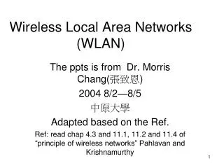
IEEE 802.11 - Wireless Local Area Networks. 802.11n. Wireless Communication Technology according to IEEE. 802.11a. 802.11h. Local wireless networks WLAN 802.11. 802.11i/e/…/w. WiFi. 802.11b. 802.11g. ZigBee. 802.15.4. 802.15.4a/b. Personal wireless nw WPAN 802.15. 802.15.5.

E N D
IEEE 802.11 - Wireless Local Area Networks Communication Technology Laboratory Wireless Communication Group
802.11n Wireless Communication Technology according to IEEE 802.11a 802.11h Local wireless networks WLAN 802.11 802.11i/e/…/w WiFi 802.11b 802.11g ZigBee 802.15.4 802.15.4a/b Personal wireless nw WPAN 802.15 802.15.5 802.15.3 802.15.3a/b 802.15.2 802.15.1 Bluetooth Wireless distribution networks/ Wireless metropolitan area nw WMAN 802.16 (Broadband Wireless Access) WiMAX + Mobility 802.20 (Mobile Broadband Wireless Access), 802.16e (WiMAX mobile) Communication Technology Laboratory Wireless Communication Group Wireless Networks
Wireless Access Technologies:Wireless Local Area Networks (WLAN) 802.11 Structure: Introduction Network architecture Reference model Physical layer MAC sublayer MAC sublayer management Communication Technology Laboratory Wireless Communication Group Wireless Networks, 802.11
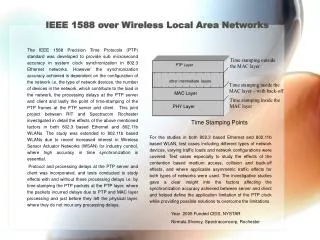
Prologue (1) • According to In-Stat and ABI Research, demand for WLAN is still expected to grow strongly over the next years. • “Faster Wi-Fi Will Grow Rapidly.”[In-Stat, 2011] • “The emerging 802.11ac standard, which is aimed at gigabit-speed wireless LANs, will be quickly adopted over the next four years…“ • “In-Stat estimates that nearly 350 million routers, client devices and attached modems with 11ac will ship annually by 2015 …” • “… 1.5 billion products equipped with 11n will be sold that year [2015], more than double the estimated 700 million in 2011.”
Prologue (2) • “800 mln WiFi households globally by 2016” [IT Facts, 2012] • “Already used in some 439 mln households worldwide, equivalent to 25% of all households, Wi-Fi home network penetration will expand to 42%, reaching nearly 800 mln by 2016.” • “58% of Americans have a mobile phone with Web connectivity.” [IT Facts, 2009] • “49.7% of Americans own smartphones” [IT Facts, 2012] • “Hotspot Usage to Reach 120 Billion Connects by 2015” [In-Stat, 2012] • “Worldwide hotspot venues will increase to over 1 million in 2013.” • “Notebooks continue to account for the majority of connects in the hotspot market; however, the rate of smartphone and tablet access is increasing rapidly.” Communication Technology Laboratory Wireless Communication Group
Prologue (3) • WLAN: fast growing market • Expanding year after year (along with the rapid spread of broadband infrastructure) • Hot Spots: WLANs at airports, railway stations, universities, cafes, etc. • Already in 2006: “82% of US hotels offer wireless Internet” • Wifi chipsets in PCs, notebooks, smartphones, tablets • Dominant standards: • IEEE 802.11g with 54 Mbit/s @ 2,4 GHz (successor of 802.11 b with11 Mbit/s @ 2,4 GHz, the former dominant standard) • The high throughput 802.11n MIMO standard • WiFi Alliance (1999/ 2000), WiFi Certification • Topics of this lecture: • Standardization • OSI reference model • PHY • MAC Communication Technology Laboratory Wireless Communication Group 6
Introduction to IEEE 802 • IEEE 802.11: WLAN – standard (’97/ ‘99) • Purpose: provide wireless connectivity to automatic machinery, equipment, or stations, which may be portable or hand-held, or which may be mounted on movingvehicles within a localarea • Differences: wired LAN / WLAN • destination location < >dest. Address • channel: wired < > wireless • portable < > mobile • CSMA/CD <> CSMA/CA • security issues, power saving ... • Other IEEE standards: • 802.2: Logical Link Control (LLC) • 802.3: CSMA / CD, Ethernet • 802.4: Token Bus, 802.5 Token Ring • IEEE802.11(3,4,5) specifies MAC and PHY layer • Physical Layer (PHY): Layer 1 of OSI basic reference model • Medium Access Control (MAC): lower half of layer 2 in OSI reference model (layer 2a) • Logical Link Control (LLC): • upper half of layer 2 (layer 2b) • can provide connection-oriented and connectionless services • flow control, sliding window, error checking, confirmation of received data • LLC standardized for all 802 MACs Communication Technology Laboratory Wireless Communication Group Wireless Networks, 802.11
IEEE 802.11 – Seamless Integration CSMA/CDEthernet Token Bus Token Ring Communication Technology Laboratory Wireless Communication Group Wireless Networks, 802.11
Network structure (1) Internet TCP/IP layered architecture 9 Wireless Networks, 802.11
LLC Quelle: MR Ethernet Network structure (2) Thanks to Maximilian Riegel, Siemens Mobile;some pictures of this lecture are taken from his presentations (formerly at http://www.max.franken.de). Communication Technology Laboratory Wireless Communication Group Wireless Networks, 802.11
Characteristics of wireless LANs • Advantages • very flexible within the reception area • mobile communications • Ad-hoc networks without previous planning possible • (almost) no wiring difficulties (e.g. historic buildings) • more robust against disasters like, e.g., earthquakes, fire - or users pulling a plug... • Disadvantages • typically very low data rate per user compared to wired networks due to shared medium • products have to follow many national restrictions if working wireless, it takes a vary long time to establish global solutions • low coverage range Wireless Networks, 802.11
Design goals for wireless LANs • Low power for battery use • No special permissions or licenses needed (ISM band) • Robust transmission technology (for the wireless channel) • Simplified spontaneous cooperation at meetings (ad hoc) • Easy to use for everyone, simple management • Security (no one should be able to read my data), privacy (no one should be able to collect user profiles), safety (e.g. low radiation) • Transparencyconcerning applications and higher layer protocols, but also location awareness if necessary • Using existing LAN infrastructure (global, seamless operation) Wireless Networks, 802.11
WLAN standardization 802.11F: Inter Access Point Protocol DFS: dynamic frequency selection TPC: transmit power control Communication Technology Laboratory Wireless Communication Group Wireless Networks, 802.11
WLAN IEEE 802.11 Structure: • Introduction • Network architecture • Reference model • Physical layer • MAC sublayer • MAC sublayer management Communication Technology Laboratory Wireless Communication Group Wireless Networks, 802.11
802.11 Network architectures • Station (STA): Any device that contains an IEEE 802.11 conformant MAC and PHY interface to the wireless medium (WM). • Basic Service Set (BSS): Set of stations controlled by a single coordination function (CF). • CF: logical function, determines when a STA operating within a BSS is permitted to transmit and may be able to receive protocol data units (PDUs) via the WM. • Station Services (SS): set of services that support transport of MAC service data units (MSDUs) between STAs within a BSS. • Independent Basic Service Set (IBSS): BSS that forms a self-contained network, and in which no access to a distribution system (DS) is available (=> Ad Hoc network) Quelle: MR Communication Technology Laboratory Wireless Communication Group Wireless Networks, 802.11
Ad Hoc Mode: 802.11 IBSS • Network composed solely of stations within mutual communication range of each other via the wireless medium (WM); typically created in a spontaneous manner. • Principal distinguishing characteristic: limited temporal and spatial extent. Quelle: MR Communication Technology Laboratory Wireless Communication Group Wireless Networks, 802.11
Quelle: MR Infrastructure Mode (1) transport layer network layer LLC (layer 2b) • Access Point (AP): Any entity that has STA functionality and provides access to the DS via the wireless medium (WM) for associated stations => AP implements both the 802.11 MAC and the DS MAC protocols. Communication Technology Laboratory Wireless Communication Group Wireless Networks, 802.11
Access Point (AP) A AP B Infrastructure Mode (2) • Several connected BSSs may form (together with integrated LANs) an Extended Service Set (ESS) • The architectural component used to interconnect BSSs is the distribution system (DS). • 802.11: Distribution System Services (DSS) are specified (not the DS itself) • The medium used by the DS is called Distribution System Medium (DSM), and is not specified. Examples are a Wireless Medium, a cable, or a fibre-optic cable, ... STA 2 Quelle: MR STA 1 Communication Technology Laboratory Wireless Communication Group Wireless Networks, 802.11
Infrastructure Mode (3) • Portal: The logical point at which MAC service data units (MSDUs) from a non-IEEE 802.11 local area network (LAN) enter the DS of an ESS. Communication Technology Laboratory Wireless Communication Group Wireless Networks, 802.11
WLAN IEEE 802.11 Structure: Introduction Network architecture Reference model Physical layer MAC sublayer MAC sublayer management Communication Technology Laboratory Wireless Communication Group Wireless Networks, 802.11
OSI basic reference model: • 802.11 specifies the layers 1 and 2a • Coexistence • with other 802 LANs (Bridge on LLC layer) • several 802.11 WLANs • Compatibility to other (802) LANs: • Mobility of STAs handled in the MAC layer; so, for upper protocol layers, 802.11 shows no differences to other 802 networks • One MAC for all 802.11 PHYs • Enhancements: 802.11e, 802.11n, … Communication Technology Laboratory Wireless Communication Group Wireless Networks, 802.11
IEEE 802.11 LLC (Logical Link Control) Reference model: Protocol Entities DATA Link MAC Sublayer MAC Sublayer Management Station Management PLCP Sublayer PHY PHY Layer Manage-ment PMD Sublayer Communication Technology Laboratory Wireless Communication Group Wireless Networks, 802.11
WLAN IEEE 802.11 Structure: Introduction Network architecture Reference model Physical layer MAC sublayer MAC sublayer management Communication Technology Laboratory Wireless Communication Group Wireless Networks, 802.11
5 different Physical layer technologies • FHSS (Frequency Hopping Spread Spectrum) • 2.4 GHz band: 1 and 2 Mbit/s, 2GFSK, 4GFSK • frequency hopping: 79 frequencies • DSSS (Direct Sequence Spread Spectrum) • 2.4 GHz band: 1, 2, 5.5 and 11 Mbit/s • DBPSK, DQPSK, 11-chip Barker Sequence, CCK • OFDM (Orthogonal Frequency Division Multiplexing) • 802.11a: 5 GHz band, 6, 9, 12, 18, 24, 36, 48 and 54 Mbit/s • BPSK, QPSK, 16-QAM and 64-QAM (each with 2 different coding rates) • 52 sub-carriers • 802.11g: OFDM in 2.4 GHz with 54 Mbit/s • Baseband IR • 1 and 2 Mbit/s, 4-PPM and 16-PPM • MIMO (Multiple Input – Multiple Output) – OFDM • 802.11n: upto 600 Mbit/s (details see 802.11n chapter) Quelle: MR Communication Technology Laboratory Wireless Communication Group
Physical Layer – OFDM , 802.11 g and 802.11n and 802.11 g IEEE 802.11 a: (in CH) OFDM@ 5.15 – 5.35 GHz (Indoor) and @ 5.47 – 5.725 GHz (Indoor&Outdoor) 802.11 g: OFDM @ 2,4 - 2,4835 GHz Communication Technology Laboratory Wireless Communication Group Wireless Networks, 802.11
Physical Layer – 802.11a. OFDM Transmitter and receiver block diagram for the OFDM PHY Communication Technology Laboratory Wireless Communication Group
802.11a PHY Data Format http://www.ewh.ieee.org/r6/scv/comsoc/0205.pdf 27
Physical Layer – OFDM (802.11a) Subcarrier frequency allocation Bandwidth: 20 MHz FFT block length : 64 Number of used carriers: 52 (including 4 pilots) Guard interval: 0.8 µs Wireless Networks, 802.11
802.11a Subcarrier Assignment http://www.ewh.ieee.org/r6/scv/comsoc/0205.pdf 30
Subcarrier Modulation Schemes modulation Correction http://www.ewh.ieee.org/r6/scv/comsoc/0205.pdf 31
Comparison of mostly used 802.11 PHYs Data rates 802.11a: OFDM, up to 54 Mbit/s 802.11b: DSSS, up to 11 Mbit/s 802.11g: DSSS (downwardly compatible to 802.11b) / OFDM (up to 54 Mbit/s) Channels 802.11a: 8 (non-overlapping) channels @ 5.15 – 5.35 GHz (20 MHz each) => up to 8 APs in the same area 802.11b/ g: only 3 non-overlapping (out of 13) channels (25 MHz each) => only up to 3 APs in the same area Communication Technology Laboratory Wireless Communication Group
Channels: 802.11b European channel selection—non-overlapping European channel selection—overlapping Communication Technology Laboratory Wireless Communication Group Wireless Networks, 802.11
Channels: 802.11a OFDM PHY frequency channel plan for the United States Communication Technology Laboratory Wireless Communication Group
WLAN IEEE 802.11 Structure: Introduction Network architecture Reference model Physical layer MAC sublayer MAC sublayer management Communication Technology Laboratory Wireless Communication Group Wireless Networks, 802.11
Overview: MAC Sublayer • Two multiple access schemes -> two Coordination Functions: (1) Distributed Coordination Function (DCF): CSMA / CA (contention based) or optional (2) Point Coordination Function (PCF): Polling (central allocation) • Different frame formats • Fragmentation / defragmentation • Encryption Communication Technology Laboratory Wireless Communication Group Wireless Networks, 802.11
Multiple access schemes Distributed Coordination Function: • For IBSS and Infrastructure mode (ESS) • Based on Carrier Sense Function in PHY, called Clear Channel Assessment (CCA) • CSMA / CA for broadcast frames • CSMA / CA + ACK otherwise • Optional: (parameterised) RTS / CTS – handshake for Virtual Carrier Sense (protection against „Hidden Nodes“) Point Coordination Function (optional): • Only in Infrastructure Mode (ESS) • Onlyfor systems using an AP as central point of BSS • AP gives transmit right to the STAs; STAs are polled one after another (Polling) • Higher priority than DCF (seeInterframe Spacing) Wireless Networks, 802.11
transmit, if medium is free >= DIFS DIFS Contention Window PIFS DIFS SIFS Backoff-Window Medium busy Slot time Next Frame Decrement Backoff Timer as long as medium idle Defer access MAC Sublayer: DCF (1) CSMA / CA (Carrier Sense Multiple Access with Collision Avoidance): • Channel access: • If WM seems to be free for a time >= DIFS, STA transmits immediately • If WM busy, STA waits until the end of the ongoing transmission and starts Backoff Procedure • After this the status of the channel is checked again Communication Technology Laboratory Wireless Communication Group Wireless Networks, 802.11
MAC Sublayer: DCF (2) • Backoff Procedure (for a STA willing to transmit): • STA sets its Backoff Timer to a random backoff time. In this time STA waits and uses carrier-sense mechanism. • Only if the WM seems to be idle, the STA decrements the Backoff Timer. • Backoff procedure starts also, if a collision is detected. • Backoff procedure reduces the probability of collisions • without such a procedure this probability would be high after a successful transmission, because then all the STAs prepared to transmit would start their transmissions at the same time. Communication Technology Laboratory Wireless Communication Group Wireless Networks, 802.11
DIFS Data Src SIFS Ack Dest Contention Window DIFS Other Next MPDU Defer transmission Backoff Procedure MAC Sublayer: DCF (4) - CSMA / CA + ACK – Protocol • In a direct transmission between 2 STAs successful transmissions (CRC correct) are acknowledged immediately (positive acknowledgement) using ACK Frames. • If no ACK is received the frame is repeated. • The (physical) Carrier-Sense mechanism is provided by the PHY (CCA). • After unsuccessful transmissions the max. backoff time increases exponentially up to a limit. Communication Technology Laboratory Wireless Communication Group Wireless Networks, 802.11
DIFS Data RTS Src CTS Ack Dest CW Next MPDU Other NAV (RTS) NAV (CTS) Backoff Procedure Defer transmission MAC Sublayer: DCF (5) - RTS-CTS Handshake (optional) • All STAs receiving at least one of the two control frames are now informed about the length of the upcoming transmission (Virtual Carrier Sense) • STAs store this information in their Net Allocation Vector (NAV) • Carrier-Sense mechanism: CCA + NAV • Control frames are exchanged: • “Ready To Send“: RTSSTA wants to start transmission • “Clear To Send”: CTSreceiver is ready for transmission • These frames contain a field indicating the length of the upcoming transmission. Communication Technology Laboratory Wireless Communication Group
STA AP RTS RTS Range CTS CTS Range Data Ack AP STAs can’t hear each other but the AP. STA STA MAC Sublayer: DCF (6) - Hidden Nodes The „Hidden Nodes“problem can be eased by the RTS / CTS mechanism. • STAs can be configured, to use the RTS / CTS mechanism always, never or from a given threshold upwards (for short frames the overhead may be too high). Communication Technology Laboratory Wireless Communication Group
Exposed Nodes • STA S1/S2 does not generate interference at STA R2/R1 • S1 and S2 on the other hand are in communication range of each other • They are „exposed nodes“ • Thus S1 and S2 could transmit simultaneously • CSMA/CA prevents this, as e.g. S2 senses the channel busy if S1 transmits • RTS/CTS can help here: if e.g. S2 detects the RTS message of S1 but does not receive the CTS answer from R1 it can conclude, that it is an exposed node and transmit concurrently with S1 45
DIFS PIFS SIFS Other Backoff NAV (RTS) NAV (Fragment 0) NAV (CTS) NAV (ACK 0) SIFS Src RTS Fragment 0 Fragment 1 Dest CTS ACK 1 ACK 0 MAC Sublayer: Fragmentation • Partitioning MSDUs (MAC Service Data Units) or MMPDUs (MAC Management Protocol Data Units) into smaller MAC level frames • Purpose: increase reliability, by increasing the probability of successful transmission • Fragmentation: MSDU or MMPDU are sent as independent transmissions, each of which is separately acknowledged (not for Broadcast frames) • Backoff procedure and retransmission if no ACK received • Information about duration of transm. included in fragments and in ACKs => NAV is set • Defragmentation at receiver • Can be combined with RTS - CTS Communication Technology Laboratory Wireless Communication Group
PCF waits when medium is busy:delay CFP repetition interval CFP repetition interval CFP CP DCF PCF WM busy CF burst (PCF) Variable length "Reset NAV" Async traffic waits NAV MAC Sublayer: PCF (1) • AP of a BSS can become Point Controller (PC) -> Polling Master • PCF gains control of the WM by using Beacon Management Frames to set the NAV in STAs • Contention Period (CP): DCF has control in this period (CSMA/CA: contention based multiple access) • Contention Free Period (CFP): PCF has control (Polling: central allocation, no contention) • CP and CFP alternate under PC control • Length and repetition interval of the CFPs are controlled by the PC Communication Technology Laboratory Wireless Communication Group
MAC Sublayer: PCF (2) • STA immediately responses to a CF-Poll_Frame • Responses have variable length • “Reset NAV“bylast frame of AP • No RTS / CTS under PCF (Polling) • PCF better suited for time critical services However, legacy PCF was rarely (or even never) used; => But, it is the basis for a CF in 802.11e Communication Technology Laboratory Wireless Communication Group Wireless Networks, 802.11
MAC Sublayer: Interframe Spacing • SIFS (Short Interframe Space):time between ACK frames, CTS frames, fragmented data frames and PCF polls. E.g.: Frequency Hopping PHY - 28ms (802.11a: 16µs) • PIFS (PCF Interframe Space):PCF has higher priority than DCF=> PIFS < DIFS; PIFS = SIFS + Slot TimeE.g.: Frequency Hopping PHY - 78ms (802.11a: 25µs) • DIFS (DCF Interframe Space):= SIFS + 2 Slot TimeE.g.: Frequency Hopping PHY - 128ms (802.11a: 34µs) • EIFS (Extended Interframe Space):used if in previous transmission an error occurred • IFS independent of the STA bit rate Communication Technology Laboratory Wireless Communication Group
WLAN IEEE 802.11 Structure: Introduction Network architecture Reference model Physical layer MAC sublayer MAC sublayer management Communication Technology Laboratory Wireless Communication Group Wireless Networks, 802.11