Download
1 / 1
10 likes | 85 Views
Study integrates model equations for three loading conditions to understand joint angles. Red shows commanded joint angles. Simulation feasibility study on posture-dependent control of stimulation. Published in JRRD. DOI: 10.1682/JRRD.2013.06.0150.

E N D
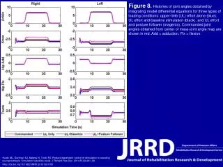
Figure 8. Histories of joint angles obtained by integrating model differential equations for three types of loading conditions: upper-limb (UL) effort alone (blue), UL effort and baseline stimulation (black), and UL effort and posture follower (magenta). Commanded joint angles obtained from center of mass-joint angle map are shown in red. Add = adduction, Flx = flexion. • Audu ML, Gartman SJ, Nataraj N, Triolo RJ. Posture-dependent control of stimulation in standing neuroprosthesis: Simulation feasibility study. J Rehabil Res Dev. 2014;51(3):481–96. • http://dx.doi.org/10.1682/JRRD.2013.06.0150