One Za’abeel Projects Case Study
50 likes | 212 Views
One Zau2019abeel Mixed-use is a famous project that is currently under construction in Dubai, UAE. Located between the Dubai World Trade Centre and Zau2019abeel Park, the One Zau2019abeel project comprises of two towers u2013 Tower A and Tower B.

One Za’abeel Projects Case Study
E N D
Presentation Transcript
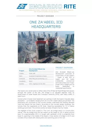
ONE STOP MONITORING SOLUTIONS | HYDROLOGY | GEOTECHNICAL | STRUCTURAL | GEODECTIC Over 50 years of Excellence through ingenuity PROJECT DOSSIER ONE ZA’ABEEL ICD HEADQUARTERS PROJECT OVERVIEW One Za’abeel Mixed Use Development Project One Za’abeel Mixed-use Development comprises of construction of two towers - Tower A with 305 m height and (residential, and hotel areas) and Tower B with 240 m height and 59 levels (dedicated residential apartments) Location Dubai, UAE Client Investment Corporation of Dubai Contractor APCC Piling and Contracting L.L.C 69 commercial levels Consultants W.S.P Duration 2015 –ongoing as of Jan 2021 to The towers are constructed on either side of the Al Saa’da Road Bridge that passes through the center of the plot. The bridge is an elevated highway road, by Government of Dubai Roads and Transport Authority (RTA), with heavy traffic in peak hours. Constyruction of seven level basement car parking in both the towers incpudes deep excavation – up to depths ranging from 25 m to 28 m depth below ground level. The basements are connected by two tunnels located underneath the existing elevated road that bisects the two towers. According to the concept design drawings, the tunnels links the basements at B1 level, requiring excavations to 7.0 m below existing ground level. The common podium at base of towers has four levels. The highlight of this iconic project is “The Link” sky bridge which is a construction marvel. This sky bridge links the two towers at the height of 105 m above ground level. It is approximately 230 m in length with cantilever of 66 m projecting from tower A, spanning in the middle of the towers. Cross section of bridge is 18 m2 and consists of four levels with viewing deck and swimming pool on the roof. www.encardio.com
WHY MONITORING? Instrumentation monitoring and surveying played a vital role in risk assessment of existing road bridge, deep excavation, tunneling, towers and the link bridge during the construction progress. The monitoring instruments provided early warning, through regular or continuous monitoring, for any excessive and undue ground movements affecting the construction or nearby infrastructure. This allowed for implementation of preventive remedial actions well within time. The monitoring system helped in reduction of risks, protecting assets& construction. MONITORING SOLUTION The monitoring work was divided into three sections 1.Existing road bridge monitoring 2.Deep excavation monitoring 3.Structure monitoring Monitoring of existing road bridge Looking at the criticality of safety monitoring of the Al Saa’da Bridge, automatic online monitoring was decided. Both at the bridge and piers, geotechnical and geodetic instruments were installed with advance automatic dataloggers to monitor effects of construction of deep excavation, tunneling and construction of the high rise buildings. Monitoring during deep excavation works This was one of the first building project in the city to have 7 basements for car park. Thus, monitoring of deep excavation was very critical. The excavation started after the completion of enabling works in which inclinometers, optical targets were installed on shoring wall to monitor the lateral movement of diaphragm wall and piezometer were installed to ensure the water table to be maintained as per the design. Monitoring of structure during construction To monitor the overall structure movement during tower construction, series of instrumentation and monitoring program were adopted and implemented on most of the floors to ensure the building behavior as predicted in model study. Strain gauge, tilt sensor and prism targets were used to measure the strains which developed on columns, lateral movement & rotation of building, building movement during construction. ENCARDIO-RITE’S ROLE Turnkey services Encardio-rite got sub-contract for the complete monitoring works that included: Supply of geotechnical instruments, precise survey instruments and targets Installation of geotechnical instruments for subsurface instruments and survey targets Online monitoring of critical parameters and areas
Automatic 3D deformation monitoring Pre-construction condition monitoring of Al Saa’da Bridge Programming and commissioning of data acquisition systems Setting up an online web-based data management system (WDMS) and maintenance during the contract period Daily & weekly reporting with evaluation & interpretation INSTRUMENT USED Instrument Purpose Existing bridge and pier monitoring Used on the bridge to monitor change in stresses in bridge due to deep excavation and dewatering nearby. Strain gages Used on piers of the bridge to monitor 3D movement of bridge to check if there is any structural impact due to ongoing site activities in close vicinity. Prism Target Used at top, bottom and sides of the bridge deck to correlate monitoring temperature changes Temperature sensor data with ambient Excavation works and ground monitoring Used to measure lateral movement due to construction activity, during deep excavation for Tower A & B at diaphragm walls, near existing bridge, near tunnel area Digital Inclinometer Used outside the excavation areas to determine the groundwater behavior before, during and after construction activities, near deep excavation works for Tower A & B, near existing bridge Standpipe Piezometer Structure monitoring (the two towers) Used on the Towers, every 10 floors to monitor 3D movements Prism Target Used at selected columns for stress measurement and also to estimate axial shortening which experiences in load-bearing concrete columns and walls Strain gages Used on selected columns of selected floors, to monitor the horizontal displacement of structure which is an important indicator to assess structural performance and safety Tilt meter Optical Laser Plummet To monitor the verticality of the structure Link bridge Used at the edges at every 20 m distance along the link bridge to monitor 3D deformation Prism Target
DATA COLLECTION AND PRESENTATION Online monitoring was done for geotechnical sensors that were critical. Data from the strain gages, temperature sensors, tiltmeter were collected and transmitted by automatic compact dataloggers. Data from prism targets was collected and transmitted at desired frequencies by automatic total stations with control boxes that had in-house developed software that allowed to control the ATS remotely. All the data was transmitted to a central server with our in-house developed web based data management system. The data was accessible to all the stake holders, in near real time, with advance alerts and warning system. Daily, weekly and monthly monitoring reports were submitted combined for geotechnical and geodetic monitoring data- including the online data as well as manually monitored data. Monitoring reports included interpretations of variations observed in instrument data with respect to the construction progress in the respective area. In case of any variation observed in data, field report or incidence report was included. The reports also included site progress pictures, instrumentation layout drawings. The comprehensive reports/alerts helped the stake holder in precise evaluation of field data and implementing preventive/corrective actions timely where required. KEY HIGHLIGHTS • Strain gage (bridge monitoring): Change in stress was obtained by multiplying the measured change in strain by the modulus of elasticity of concrete. As the road bridge had busy traffic, monitoring was critical. As decided by the Consultant, the strain gages were monitored every 15 minutes with automatic dataloggers. The data was transmitted in real time to our database management system. All the stake holders could view the data in meaningful information, at their desktops, laptops, notepads or mobile phone. Moving average of the data was considered, to ensure accuracies and address 'outliers' like traffic movements on bridge, temperature effect, heavy vehicle movements for construction, etc. • Prism targets (bridge monitoring): The ones installed on bridge piers were monitored using 3 numbers of automatic total stations and complex control boxes with 20 min monitoring frequency.
• Water level (deep excavation monitoring): De-watering monitoring was very critical. It could be too fast or too slow; else it risked effecting the ground conditions, resulting in structural movement. Thus, cross effects of water levels was interpreted with any detected movement. • Laser Plummet (structure monitoring): This was the first experience of Encardio-rite with structure verticality monitoring which was successfully accomplished. The horizontal alignment of the structure was monitored along a vertical axis by using a high accuracy Geo Laser plummet having an accuracy of ±1 mm ~ 3 mm/200 m. To establish a Vertical Axes Network, ten openings on each slab of Tower A & B, were made without any obstruction from bottom to top. Every measurement in the grid was recorded as the monitoring reading. It was then converted into picture, recorded and sent to the data base. Each hole had a unique code shown in each picture. The picture also included day, time, position and measurement (laser projection). This prevented any risk of error. CHALLENGES Monitoring of Link Bridge was challenging as it was difficult to have line of sight for monitoring the prism targets used for 3D movement of the bridge. Monitoring the verticality of such high towers was quite challenging. Installation of strain gages in the existing bridge was challenging, as installation was done inside bridge viaduct with confined space and little natural light from the service openings. No artificial sources of lighting could be used. A lot of preparation work was done by team following the ‘confined space safety norms’ Maximizing the baseline data was challenging. One had to understand the seasonal adjustments and effects. Also the team had to handle unexpected factors that affected the monitoring conditions. For example, there was a temperature variation of 4.4°C during 13th-27th November, which was an unusual variation in such a short period for this geographical location. Changing line of site for optical surveying, as construction works progressed, posed a challenge. Survey team tried to pre-determine the line of sight with modelling software, thinking ahead about the access formonitoring. Due to construction activities, dirt used to deposit on the prism targets. Cleaning the prisms at height at regular intervals was challenging, as it required pre-planning to get lifting equipment for access Power source for the automatic total stations (ATS) and control boxes became challenging as they were fixed in the median. Thus, direct power from power line could not be given. Diesel generator had issues of power drop outs, or sudden surges, due to which some data was lost. It was decided to use solar power, but solar panel again lost charging due to mist. Finally team designed a system to have 3 day autonomy combined with diesel generator and solar panels. RESULT Encardio-rite’s World class instruments and expertise in the field helped to monitor such iconic structure meeting the precision standards required for the project. Monitoring data was made available to all stakeholders seamlessly almost in the real time, in meaningful information, with advance warnings and alerts. This was possible with a combination of rugged sensors, advanced data collection, transmission and web-based data monitoring service. The monitoring results helped in reducing risks, protecting existing assets and giving confidence to the construction process and successful completion of the project. Thus, the role of instrumentation and monitoring in the project was not only limited to design optimization and construction control but also to ensure the safety and stability of work at construction site and of the infrastructure within zone of influence. ENCARDIO-RITE ELECTRONICS PVT. LTD. A-7, Industrial Estate, Talkatora Road Lucknow, UP - 226011, India | P: +91 522 2661039-42 | Email: geotech@encardio.com | www.encardio.com International: India | Bhutan | Bahrain | Qatar | UAE | Morocco | Greece | Spain | UK | USA India: Lucknow | Delhi | Kolkata | Mumbai | Chennai | Bangalore | Hyderabad | J&K