Download
1 / 23
230 likes | 393 Views
This lecture covers topics such as finite state machines, gate level modeling, and verilog hardware description language. It also discusses the design of finite state machines and the use of flip flops in digital systems design.

E N D
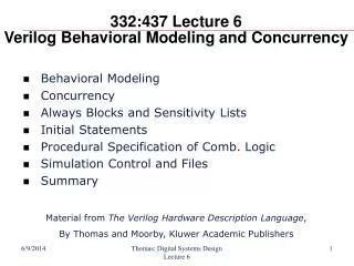
332:437 Lecture 8Verilog and Finite State Machines • Finite State Machines • Discrete Time Simulation • Gate Level Modeling • Delays • Summary Material from The Verilog Hardware Description Language, By Thomas and Moorby, Kluwer Academic Publishers Thomas: Digital Systems Design Lecture 8
outputs inputs FSM clock reset Finite State Machines — Review • In the abstract, an FSM can be defined by: • A set of states or actions that the system will perform • The inputs to the FSM that will cause a sequence to occur • The outputs that the states (and possibly, the inputs) produce • There are also two special inputs • A clock event, sometimes called the sequencing event, that causes the FSM to go from one state to the next • A reset event, that causes the FSM to go to a known state Thomas: Digital Systems Design Lecture 8
We’ll talk about how to design this outputs Combinational Logic inputs next state Current State Register clock reset We’ll talk about what these are FSM Review • The traditional FSM diagram • We looked at State Transition Diagrams (and Tables) last time • … and ended up with a diagram that looked like this Thomas: Digital Systems Design Lecture 8
Current state (now) Next state, after clock event Q 0 1 0 1 Q+ 0 0 1 1 D 0 0 1 1 Verilog for the D Flip-Flop Note that it doesn’t matter what the current state (Q) is. The new state after the clock event will be the value on the D input. module DFF (output reg q, input d, clk, reset); always @(posedge clk or negedge reset) if (~reset) q <= 0; else q <= d; endmodule The change in q is synchronized to the clk input. The reset is an asynchronous reset (q doesn’t wait for the clk to change). Thomas: Digital Systems Design Lecture 8
D Q C clk Current state, now Next state, after clock event Positive edge triggered Flip Flop D 0 0 1 1 Q 0 1 0 1 Q+ 0 0 1 1 D Q C clk Negative edge triggered Flip Flop (bubble indicates negative edge) Clock Events on Other Planets • Trigger alternatives • For flip flops, the clock event can either be a positive or negative edge • Both have same next-state table Thomas: Digital Systems Design Lecture 8
Q2 Q1 D1 Z reset X Q1 Q2 D2 Q2’ reset clock reset Moore Machine — 111 Detector • Note how the reset is connected • Reset will make both of the FFs zero, thus putting them into state A. • Most FFs have both reset and “preset’’ inputs (preset sets the FF to one). • The reset connections (to FF reset and preset) are determined by the state assignment of the reset state. Thomas: Digital Systems Design Lecture 8
Q2 Q1 D1 Z reset X Q1 Q2 D2 Q2’ reset clock reset Verilog Organization for FSM • Two always blocks • One for the combinational logic — next state and output logic • One for the state register Thomas: Digital Systems Design Lecture 8
Verilog Behavioral Specification module FSM (x, z, clk, reset); input clk, reset, x; output z; reg [1:2] q, d; reg z; endmodule • Things to note • reg [1:2] — matches numbering in state assignment (Q2 is least significant bit in counting) • <= vs. = always @(posedge clk or negedge reset) if (~reset) q <= 0; else q <= d; The sequential part (the D flip flop) The combinational logic part next state output always @(x or q) begin d[1] = q[1] & x | q[2] & x; d[2] = q[1] & x | ~q[2] & x; z = q[1] & q[2]; end Thomas: Digital Systems Design Lecture 8
Processes Without Sensitivity List or wait Statement • Run forever – example: always begin x <= a and b and c; end Thomas: Digital Systems Design Lecture 8
Synopsys Deletes All Useless Hardware from Your Design • Synthesis: Since x can never be other than 0, hardwire x to 0 • Moral: • Signals are not updated until end of process even if they change in the middle of it due to <= operator • Expressions based on current value of signals on RHS of <= symbol • Signals updated with value in last assignment statement in process • Order of concurrent signal assignment statements is of no consequence Thomas: Digital Systems Design Lecture 8
Benefit of Don’t Cares • Don’t care condition produces less hardware • y <= s1 + s0 • Rather than • y <= s1 s0 + s1 s0 s1 s0 s1 s0 Thomas: Digital Systems Design Lecture 8
Verilog Overview • Verilog is a concurrent language • Aimed at modeling hardware — optimized for it! • Typical of hardware description languages (HDLs), it: • Controls time • Provides for the specification of concurrent activities • Stands on its head to make the activities look like they happened at the same time — Why? • Allows for intricate timing specifications — Why? • A concurrent language allows for: • Multiple concurrent “elements” • An event in one element to cause activity in another. (An event is an output or state change at a given time) • Based on interconnection of the element’s ports • Logical concurrency — software • True physical concurrency — e.g., “<=” in Verilog Thomas: Digital Systems Design Lecture 8
Discrete Time Simulation • Discrete Time Simulation • Models evaluated and state updated only at time intervals — n • Even if there is no change on an input • Even if there is no state to be changed • Need to execute at finest time granularity • Might think of this as cycle accurate — things only happen @(posedge clock) • You could do logic circuits this way, but either: • Lots of gate detail lost — as with cycle accurate above (no gates!) • Lots of simulation where nothing happens — every gate is executed whether an input changes or not. • Discrete Event Simulation… • Picks up simulation efficiency due to its selective evaluation • Only execute models when inputs change Thomas: Digital Systems Design Lecture 8
B A C Discrete Event (DE) Simulation • Discrete Event Simulation • Events — changes in state at discrete times. These cause other events to occur • Only execute something when an event has occurred at its input • Events are maintained in time order • Time advances in discrete steps when all events for a given time have been processed • Quick example • Gate A changes its output. • Only then will B and C execute • Observations • The elements in the diagram don’t need to be logic gates • DE simulation works because there is a sparseness to gate execution — maybe only 12% of gates change at any one time. • The overhead of the event list pays off then. Thomas: Digital Systems Design Lecture 8
B A C Observations • Hmm… • Implicit model execution of fanout elements • Implicit? • Concurrency — is it guaranteed? How? • Time — a fundamental thingie • Can’t you represent this all in C? After all, the simulator is written in it! • Or assembly language? • What’s the issue? • Or how about Java? Ya-know, aren’t objects like things you instantiate just like in Verilog? • Can’t A call the port-2 update method on object B to make a change? Thomas: Digital Systems Design Lecture 8
A Gate Level Model • A Verilog description of an SR latch module nandLatch (output q, qBar, input set, reset); nand #2 g1 (q, qBar, set), g2 (qBar, q, reset); endmodule A module is defined name of the module Draw the circuit The module has ports that are typed type and delay of primitive gates primitive gates with names and interconnections Thomas: Digital Systems Design Lecture 8
A Gate Level Model • Things to note: • It doesn’t appear “executable” — no for loops, if-then-else, etc. • It’s not in a programming language sense, rather it describes the interconnection of elements • A new module made up of other modules (gates) has been defined • Software engineering aspect — we can hide detail module nandLatch (output q, qBar, input set, rese)t; nand #2 g1 (q, qBar, set), g2 (qBar, q, reset); endmodule Thomas: Digital Systems Design Lecture 8
a nand #(3, 4, 5) (c, a, b); c b — transport delay rising delay delay to z falling delay Kinds of Delays • Transport delay • Input to output delay (sometimes “propagation”) • Zero delaymodels (all transport delays = 0) • Functional testing • There’s no delay, not cool for circuits with feedback! • Unit delaymodels (all transport delays = 1) • All gates have delay 1. OK for feedback • Edge sensitive — delay is value sensitive Thomas: Digital Systems Design Lecture 8
sum carryOut list of gate instances of same function implicit wire declarations aInput carryIn bInput Some More Gate Level Examples instance names and delays optional • An adder module adder (output carryOut, sum, input aInput, bInput, carryIn); xor (sum, aInput, bInput, carryIn); or (carryOut, ab, bc, ac); and (ab, aInput, bInput), (bc, bInput, carryIn), (ac, aInput, carryIn); endmodule ab bc ac Thomas: Digital Systems Design Lecture 8
Adder With Delays • An adder with delays module adder (output carryOut, sum, input aInput, bInput, carryIn); xor #(3, 5) (sum, aInput, bInput, carryIn); or #2 (carryOut, ab, bc, ac); and #(3, 2) (ab, aInput, bInput), (bc, bInput, carryIn), (ac, aInput, carryIn); endmodule each AND gate instance has the same delay Thomas: Digital Systems Design Lecture 8
Adder, Continuous Assign • Using “continuous assignment” • Continuous assignmentallows you to specify combinational logic in equation form • Anytime an input (value on the right-hand side) changes, the simulator re-evaluates the output • No gate structure is implied — logic synthesis can design it. • The description is more abstract • A behavioral function may be called — details later module adder (output carryOut, sum, input aInput, bInput, carryIn); assign sum = aInput ^ bInput ^ carryIn, carryOut = (aInput & bInput) | (bInput & carryIn) | (aInput & carryIn); endmodule Thomas: Digital Systems Design Lecture 8
I’m Sick of This Adder • Continuous assignment assigns continuously • Delays can be specified (same format as for gates) on whole equation • No instances names — nothing is being instantiated. • Given the same delays in this and the gate-level model of an adder, there is no functional difference between the models • FYI, the gate-level model gives names to gate instances, allowing back annotation of times. module adder (output carryOut, sum, input aInput, bInput, carryIn); assign #(3, 5) sum = aInput ^ bInput ^ carryIn; assign #(4, 8) carryOut = (aInput & bInput) | (bInput & carryIn) | (aInput & carryIn); endmodule Thomas: Digital Systems Design Lecture 8
Summary • Finite State Machines • Discrete Time Simulation • Gate Level Modeling • Delays • Summary Thomas: Digital Systems Design Lecture 8