Download

1 / 33
330 likes | 457 Views
This paper presents the essential components and concepts necessary for implementing single-moded and multi-moded delay line distribution systems (DLDS) in RF pulse compression and transport systems. It details the use of wrap-around mode converters within over-moded rectangular waveguides and discusses both experimental setups and theoretical modeling. Key components including mode extractors, launchers, and high-power setups are outlined, focusing on efficient RF power distribution specifically for klystron applications in accelerator technology. Various scenarios and configurations are examined for optimal performance.

E N D
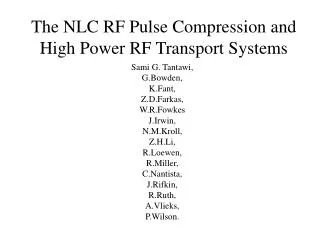
Rf Pulse Compression and Transport Systems Sami G. Tantawi
Outline Single Moded Delay Line Distribution System Components required to implement the system Components Based on the wrap-around mode converter components based on over-moded rectangular waveguides Multi-Moded Delay Line Distribution System Components required to implement the system (Launcher and Extractor) Components based on the wrap-around mode converter Components based on over-moded rectangular waveguides Experimental and Theoretical development tools. Over-moded test setup Scattering Matrix Codes High power test setups
TE01 TE12 (Vertically Polarized) TE12 (Horizontally Polarized) ~12.7 cm Circular Waveguide TE01 TE12 (Vertically Polarized) Klystrons TE01 Mode Extractor (Power is Extracted Evenly Between Four Waveguides) ~7.4 cm Circular Waveguide TE01 Mode Extractor TE01 Accelerator Structure (~1.8 m) TE21 ~ 6 m TE01 Mode Converter (Fed by Four Rectangular Waveguides) TE01 Tap-Off Mode Launcher (Fed by Four Rectangular Waveguides) TE12 to TE01 Mode Converter TE21-TE01 Mode Converter ~53 m
TE01 TE12 (Vertically Polarized) TE12 (Horizontally Polarized) TE01 TE12 (Vertically Polarized) Klystrons ~7.4 cm Circular Waveguide ~12.7 cm Circular Waveguide TE01 Mode Extractor TE01 Mode Extractor (Power is Extracted Evenly Between Four Waveguides) TE01 ~ 6 m TE01 Mode Converter (Fed by Four Rectangular Waveguides) TE01 Tap-Off TE12 to TE01 Mode Converter TE21-TE01 Mode Converter TE21 Mode Launcher (Fed by Four Rectangular Waveguides) SLAC KEK
RF Power Sources RF A Cluster of 9 Multi-Moded DLDS Sections e+ or e- Eight 75-megawatt klystrons Delay Lines Accelerator Structures A Single Multi-Moded Delay Line RF Distribution System
Single-moded System Relative Cost Efficiency Waveguide Diameter (cm) Relative Cost Multi-Moded System Efficiency Waveguide Diameter (cm)
TE11 (Vertical) TE12 (Horizontal) TE01 TE11 (Vertical) TE01 TE11 (Vertical) TE11 (Horizontal) TE01 To Accelerator Structures TE01 Launcher TE01 Extractor Extractor Schematic Diagram
~12.7 cm Circular Waveguide Klystron Load ~7.4 cm Circular Waveguide Mode Launcher (A set Of 4 hybrids) ~53 m Single-moded DLDS Tantawi 8/97
Wrap-Around Mode Converter for Tap-off, and extraction, tested to 320MW
TE01 Launcher TE01 Launcher TE11 Launcher Both Polarizations of TE11 TE01 2” TE01 Modular Launcher
TE12-TE11 Mode Converter TE11-TE01 Mode Converter TE12-TE11 Mode Converter 5” TE01 Mode Extractor
Instead of using a cutoff section to allow the extraction of the TE01 mode, one can use two mode converters cascaded together
A short circuit Y0=1 Y0=1 Y0=1 Port 3 Port 2 Y0=1 Y0=1 Port 1 Port 4 Y0=1 Y0=1 Y0=1 If a signal is injected in port 1, it will all appear in port 3.
TE12-TE01 Mode Converter TE01 Mode Extractor Compact Mode Extractor
Mode Pre-launcher, for testing launchers. The output phase of the four-waveguide output is controlled by the choice between the two inputs
~7” 1.5” A bend based on transition from an over-moded rectangular waveguide to a circular waveguide
TIMING • Because the rf power is being injected at different times into different modes that have different group velocities, one must pay a special attention to timing. The set of equation that need to be satisfied so that the each accelerator structure set get an rf pulse for a duration at the appropriate time are: • (1) • where L is the distance between accelerator structure sets, L1 is the distance between the launcher and first extractor, L2 is the distance between first and second extractor, L3 is the length of the delay line after the second extractor, vTE01 and vTE12 are the group velocities of the TE01 and TE12 modes respectively, and through are the delays due to the transmission of power from the main rf delay line system to the accelerator structure sets, i.e., the delay through and after the extractors. • There are several choices for the lengths L, L1 through L3, and through that satisfy the above set of equations. An attractive choice is to set L1 through L3 equal to L, == and • (2) • This would lead to a fairly symmetric system.
LAUNCHER • Several ideas for the launcher have been proposed (8-9). In all of them a fundamental property of the launcher has been preserved: the launcher has only four inputs and the launcher has to launch four and only four modes. If this is preserved and the launcher is matched for all four different input conditions, because of unitarity and reciprocity the scattering matrix representing the launcher has to take the following form: • (3) • This form forces the isolation between inputs; i.e., if one of the four power supplies drops out or fails, the rest of the power supplies will not receive any reflected power.
Advanced Concepts Distributed Elements Circulators Switches
Summary DLDS concepts are well understood Components based on wrap-around mode converters are being build and tested Devices based on Rectangular to Circular transitions are being designed High power experimental setups are being prepared