Download
1 / 31
310 likes | 476 Views
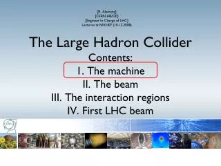
[R. Alemany] [CERN AB/OP] [Engineer In Charge of LHC] Lectures at NIKHEF (10.12.2008). The Large Hadron Collider Contents: 1. The machine II. The beam III. The interaction regions IV. First LHC beam. I. The machine. Contents: Basic layout of the machine Energy stored in the magnets

E N D
[R. Alemany] [CERN AB/OP] [Engineer In Charge of LHC] Lectures at NIKHEF (10.12.2008) The Large Hadron ColliderContents:1. The machineII. The beamIII. The interaction regionsIV. First LHC beam
I. The machine Contents: • Basic layout of the machine • Energy stored in the magnets • Quench protection system • Energy extraction • Power interlock controller • Energy stored in the beams • Beam dump system • Collimation system • Overview of the Beam Interlock System Machine Protection System
I.I Basic layout of the machine SPS (~7 km) IT LHC (27 km) IP Sector MS DS IR ARC
I.I. Basic layout of the machine: the arc LHC arc cells = FoDo lattice* with ~ 90º phase advance per cell in the V & H plane o o F D Beam Beam F D LHC TDR MB: main dipole MQ: main quadrupole MQT: Trim quadrupole MQS: Skew trim quadrupole MO: Lattice octupole (Landau damping) MSCB: Skew sextupole + Orbit corrector (lattice chroma+orbit) MCS: Spool piece sextupole MCDO: Spool piece octupole + Decapole BPM: Beam position monitor * BH lectures (tomorrow)
I.I. Basic layout of the machine • Superconducting cables of Nb-Ti 6 µm Ni-Ti filament • Superfluid helium 1 mm LHC ~ 27 km circumf. with 20 km of superconducting magnets operating @8.3 T. An equivalent machine with normal conducting magnets would have a circumference of 100 km and would consume 1000 MW of power we would need a dedicated nuclear power station for such a machine. LHC consumes ~ 10% nuclear power station
I.I. Basic layout of the machine: main dipoles • The geometry of the main dipoles (Total of 1232 dipoles in LHC) Length of the bend part =14.3 m VERTICAL PLANE HORIZONTAL PLANE Quadrupole bus-bars Heat exchanger Superconducting coils The theoretical shape of the beam channels is a straight line, while the natural shape has ~ 0.3 mm deflection between two supports at 5.4 m distance • Beam pipe (1015 H2/m3) Collars ρ = 2.8 km (R = 4.3 km) Vacuum vessel (10-6 mbar) Beam screen Distance between apertures = 194.5 mm Dipole bus-bars Iron yoke L ~ 15 m 8.3 T, 11.87 kA T = 1.9 K, ~27.5 ton Thermal shield The active part of the cold mass is bent in the horizontal plane with an angle of 5.09 mrad with ρ = 2.8 km. The shape of the two beam channels is identical.
I.I. Basic layout of the machine: main dipoles • The magnetic field of the main dipoles: the stability of the geometry of the superconducting coils is essential to the field homogeneity. Mechanical stress during coil assembly, thermal stresses during cool-down and electromagnetic stresses during operation athe the sources of deformations of the coil geometry. Additional sources of field-shape erros are the dimensional tolerances of the manet components and of the manifacturing and assembling tooling. The relative variations of the integrated field and of the field shape imperfections must not exceed ~ 10 -4 and their reproducibility better than 10 -4 . This is possible if the coil geometry is accurate, reproducible and symmetric and if the structural stability of the magnet assembly during powering is guarantee.
I.I. Basic layout of the machine: main quadrupoles 55 per sector 56 mm (warm) 194 mm (cold) Integrated gradient = 690 T Nominal gradient = 223 T/m Inominal = 11.87 kA L=3.1 m BH Lecture
I.I. Basic layout of the machine: dipole corrector magnets They correct the sextupole, octupole and decapole components of the dipole field o o F D MCS MCDO 5.8 cm LHC TDR MCD: Nominal main field strength ~ 120 T/m4 Inominal = 550 A, 1.9 K, L=11 cm, ~6 kg MCO: Nominal main field strength = 8200 T/m3 Inominal = 100 A, 1.9 K, L=11 cm, ~6 kg Nominal main field strength = 1630 T/m2 Inominal = 550 A, 1.9 K, L=15.5 cm, ~10 kg
I.I. Basic layout of the machine: quadrupole corrector magnets o o F D MSCB Orbit MQT/MQS BH Lectures (tomorrow) Landau damping LHC TDR Chromaticity MO MSM (sextupole): Nominal main field strength = 4430 T/m2 Inominal = 550 A, 1.9 K, L=45.5 cm, ~83 kg MCBM (dipole): Nominal main field strength = 2.93 T Inominal = 55 A, 1.9 K, L=78.5 cm, ~143 kg MO: Nominal main field strength = 63100 T/m3 Inominal = 550 A, 1.9 K L=38 cm, ~8 kg MQT/MQS: Nominal main field strength = 123 T/m Inominal = 550 A, 1.9 K L=38 cm, ~250 kg
I.I. Basic layout of the machine: quadrupole corrector magnets
I.I. Basic layout of the machine: Dispersion suppression DS LSS ARC The dispersion suppression is located at the transition between the arc and the straight section. The schema above applies to all DS except the ones in IR3 and IR7. Functions: • Adapts the LHC reference orbit to the LEP tunnel geometry • Cancels the horizontal dispersion generated on one side by the arc dipoles and on the other by the separation/recombination dipoles and the crossing angle bumps • Helps in matching the insertion optics to the periodic solution of the arc It is like an arc cell but with one missing dipole because of lack of space. If only dipoles are used they cannot fully cancel the dispersion, just by a factor 2.5. Therefore individual powered quadrupoles are required (Q8-Q11 with I ~ 6000 A). Q11 Q10 Q9 Q8 MBARC empty BH Lecture (tomorrow)
I.I. Basic layout of the machine: Dispersion suppression • Quadrupole types: MQ, MQM, MQTL MQM 5 m Nominal gradient = 200/160 T/m Inominal = 5.4/4.3 kA Lmag=2.4/3.4/4.8 m T=1.9/4.5 K Cold bore = 53/50 mm Individual powered apertures
I. The machine Contents: • Basic layout of the machine • Energy stored in the magnets • Quench protection system • Energy extraction • Power interlock controller • Energy stored in the beams • Beam dump system • Collimation system • Overview of the Beam Interlock System
I.II. Energy stored in the magnets ~ 10 Gjoule* (only in the main dipoles) corresponds to … … an aircraft carrier at battle-speed of 55 km/h The energy of ~3 Tons TNT The energy of 370 kg dark chocolate More important than the amount of energy is … How fast (an safe) can this energy be released? *E=1/2LI2 L: inductance ~0.1 Henry for LHC dipoles
During magnet test campaign, the 7 MJ stored in one magnet were released into one spot of the coil (inter-turn short) P. Pugnat I.II. Energy stored in the magnets: quench If not fast and safe …
I.II. Energy stored in the magnets: quench • A quench is the phase transition of a super-conducting to a normal conducting state • Quenches are initiated by an energy release of the order of mJ: • Movement of the superconductor by several µm (friction and heat dissipation) • Beam losses: • @7 TeV 0.6 J/cm3 can quench a dipole; this energy density can be generated by 107 protons; • @450 GeV (injection energy), 109 prootons are needed • Cooling failure
I.II. Energy stored in the magnets: Quench Protection System (QPS) • To limit the temperature increase after a quench • The quench has to be detected Quench Detectors* • The energy is distributed in the magnet by force-quenching the coils using Quench Heaters* • The stored energy is released in a controlled way Cold by-pass diodes* and Energy Extraction System • Failure in the QPS system: • False quench detection: down time some hours • Missed quench: damage of magnets, down time 30 days Quench Protection System * On every SC magnet
I.II. Energy stored in the magnets: Quench Protection System • Schematics of the QPS in the main dipoles of a sector Quench Detectors V1-V2 ≠ 0 Cold diode R Power Converter L1(SC Magnet) L2(SC Magnet) L154(SC Magnet) Switch Quench Heaters R (Energy Extraction)
I.II. Energy stored in the magnets: Energy Extraction System (EES) • During normal operation every ramp down of the magnets implies energy extraction, but this takes ~ 20 min too slow in case of a quench. • A dedicated Energy Extraction System for quench protection is needed. • There are 32 EES for the 24 13 kA main circuits (dipoles + quadrupoles) (+ the EES for the 600 A correctors). Resistors Switches • The EES releases the energy in 104 s for the dipoles (-125 A/s) and in 40 s for the quadrupoles (-325 A/s).
Power Converters QPS Cryo UPS, AUG If circulating beam I.II. Energy stored in the magnets: Power Interlock Controller (PIC) • 36 PICs in LHC for the SC magnets (warm magnets also have PICs) • 1 PIC per Powering Subsector
I. The machine Contents: • Basic layout of the machine • Energy stored in the magnets • Quench protection system • Energy extraction • Power interlock controller • Energy stored in the beams • Beam dump system • Collimation system • Overview of the Beam Interlock System
Enough to melt 500 kg of copper I.III. Energy stored in the beams Ep+ = 7 TeV Kb = 2808 Num p+/bunch = 1.15 x 10¹¹ Ebeam = 362 MJoules 25 ns Ebeam = Ep+ x Kb x Num p+/bunch Nominal values
Increase with respect to existing accelerators : • A factor 2 in magnetic field • A factor 7 in beam energy • A factor 200 in stored energy ALICE ATLAS LHCb CMS LHC I.III. Energy stored in the beams
Beam Dump Block H-V kicker for painting the beam Septum magnet deflecting the extracted beam 15 kicker magnets I.III. Energy stored in the beams: Beam Dump System (LBDS) Is the only system in LHC able to absorb the full nominal beam Beam Dump Block (graphite) ~ 8 m IR6 concrete shielding
I.III. Energy stored in the beams: Beam Dump System (LBDS) 10th sep 08
I.III. Energy stored in the beams: Collimation System 56.0 mm 1 mm +/- 6 = 3.0 mm Collimation system functionality: Absorb beam halo to avoid quenches Once beam losses appear, they protect the equipment and the experiments. If BLM > threshold Beam Interlock Beam Dump System E.g. Settings of collimators @7 TeV with luminosity optics Very tight settings orbit feedback!!
I. The machine Contents: • Basic layout of the machine • Energy stored in the magnets • Quench protection system • Energy extraction • Power interlock controller • Energy stored in the beams • Beam dump system • Collimation system • Overview of the Beam Interlock System
I.IV. Beam Interlock System Overview Beam Current Current Safe LHC Monitors Energy Energy Energy Parameters DCCT Dipole Injection Current 1 SPS Extraction Beam Energy Kickers Interlocks Tracking SafeBeam DCCT Dipole Flag Current 2 TL collimators RF turn clock BLMs aperture Beam Dumping System BLMs arc Collimators / Absorbers Beam Dump Trigger Access Safety BPMs for Beam Dump System NC Magnet Interlocks Discharge LHC BPMs for dx/dt + dy/dt Switches Beam dI/dt beam current Interlock System dI/dt magnet current Cryogenics essential RF + Damper circuits Quench LHC Experiments Protection Powering Interlock Vacuum System auxiliary System circuits Power Converters Screens Operators AUG Timing Software Interlocks UPS
I.IV. Beam Interlock System Overview BIS USER SYSTEMS Beam ‘Permit’ Signals User ‘Permit’ Signals LHC Beam Dump System 153 User Systems distributed over 27 km