Download
1 / 23
250 likes | 650 Views
Learn about Exhaust Gas Recirculation (EGR) in automotive engines, NOx formation, controlling methods, EGR system operation, testing, position sensors, digital valves, OBD-II monitoring, diagnostic strategies, and symptoms of a defective EGR system.

E N D
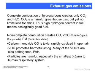
NOX FORMATION • Nitrogen (N2) and oxygen (O2) molecules are separated into individual atoms of nitrogen and oxygen during the combustion process. • These then bond to form NOX (NO, NO2). • When combustion flame front temperatures exceed 2,500°F (1,370°C), NOX formation increases dramatically.
CONTROLLING NOX • The amounts of NOX formed at temperatures below 2,500°F (1,370°C) can be controlled in the exhaust by a catalyst. • To handle the amounts generated above 2,500°F (1,370°C), the following are some methods that have been used to lower NOX formation: • Enrich the air-fuel mixture. • Lower the compression ratio. • Dilute the air-fuel mixture.
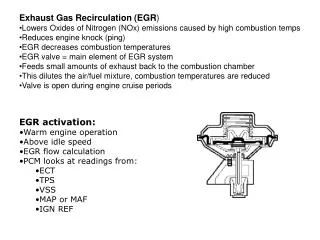
EGR NOT REQUIRED • Because combustion temperatures are low, EGR is usually not required during the following conditions. • Idle speed • When the engine is cold
EGR SYSTEM OPERATION • Since small amounts of exhaust are all that is needed to lower peak combustion temperatures, the orifice that the exhaust passes through is small. • When the EGR valveopens, exhaust flows through the valve and into passages in the intake manifold
TESTING Vacuum supply (except eletronic) Diaphragm integrity Intake to exhaust passages Control system
LATE MODEL Typical vacuum-operated EGR valve. The operation of the valve is controlled by the computer by pulsing the EGR control solenoid on and off.
COMPUTER-CONTROLLED EGR • Many computer-controlled EGR systems have one or more solenoids controlling the EGR vacuum. • The computer controls a solenoid to shut off vacuum to the EGR valve at cold engine temperatures, idle speed, and wide-open throttle operation. • Always check theory & operation of the system you are working with • Look in emission control manual (best), AllData, Mitchell &, of course, Google
EGR VALVE POSITION SENSORS • Late model computer-controlled EGR systems use a sensor to indicate EGR operation. • On-Board Diagnostics Generation-II (OBD-II) EGR system monitors require an EGR to determine EGR gas flow. • A linear potentiometer on the top of the EGR valve stem indicates valve position for the computer. • This is called an EGR valve position (EVP) sensor.
DIGITAL EGR VALVES • Unlike the previously mentioned vacuum-operated EGR valves, the digital EGR valve consists of three solenoids controlled by the PCM. • uses three solenoids for EGR. • A scan tool can be used to turn on each solenoid to check if the valve is working and if the exhaust passages are capable of flowing enough exhaust to the intake manifold to affect engine operation when cycled .
EGR VALVE POSITION SENSORSLinear EGR • General Motors and several others vehicles use a linear EGR that contains a pulse-width modulated solenoid to precisely regulate exhaust gas flow and a feedback potentiometer that signals to the computer the actual position of the valve.
OBD-II EGR MONITORING STRATEGIES • In 1996, the U.S. EPA began requiring OBD-II systems in all passenger cars and most light-duty trucks. • These systems include emissions system monitors that alert the driver and the technician if an emissions system is malfunctioning. • To be certain the EGR system is operating, the PCM runs a functional test of the system, when specific operating conditions exist. • The OBD-II system tests by opening and closing the EGR valve. • The PCM monitors an EGR function sensor for a change in signal voltage. • If the EGR system fails, a diagnostic trouble code (DTC) is set. If the system fails two consecutive times, the malfunction indicator light (MIL) is lit.
OBD-II EGR MONITORING STRATEGIES FIGURE 27-9 A DPFE sensor and related components.
OBD-II EGR MONITORING STRATEGIES FIGURE 27-10 An OBD-II active test. The PCM opens the EGR valve and then monitors the MAP sensor and/or engine speed (RPM) to meet acceptable values.
DIAGNOSING A DEFECTIVE EGR SYSTEM • If the EGR valve is not opening or the flow of the exhaust gas is restricted, then the following symptoms are likely: • Ping (spark knock or detonation) during acceleration or during cruise (steady-speed driving) • Excessive oxides of nitrogen (NOX) exhaust emissions If the EGR valve is stuck open or partially open, then the following symptoms are likely: • Rough idle or frequent stalling • Poor performance/low power, especially at low engine speed • Confirm EGR flow, the intake manifold vacuum @ idle should drop 6 to 8 in. Hg when the EGR is activated
MAKE SURE THE PORTS ARE CLEAR Removing the EGR passage plugs from the intake manifold on a Honda.