Download
1 / 59
590 likes | 695 Views
Join our multidisciplinary team for a collaborative building project at Express University in Phoenix, AZ. Emphasizing discipline knowledge and technology application, work together to preserve rare cacti on site. Explore conceptual design aspects and structural options for the engineering school through early collaboration to achieve simplicity, functionality, and budget considerations.

E N D
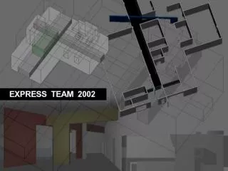
Team Introduction construction manager Kit Fleming architect Xiang Liu engineer Peng Li owner Hans Verheij Collaboration in Cyberspace E X P R E S S T E A M 2 00 2 . C E E 2 2 2 . A E C G L O B A L T E A M C L A S S 2 0 0 2
Project Goal • Multi-disciplinary, collaborative teamwork in a building project • Apply discipline knowledge and technologies. • Knowledge management. Requirements • The year is 2015 • A 3-story building • Total fund, $5,500,000 • Maintain the footprint of the existing buildings • A collection of rare cactus varieties about 16,000 square feet is protected by the “Society Environmental Desert Studies.”
Site Map The site map of new engineering school • Location • Express University is located in Phoenix, Arizona. • Climate/Weather • Annual average temperature is 61F. • Annual rainfall is 7.6 inch The campus map of Express University
Analysis of Context • Good use of materials • Insulation Concerns • Aesthetic taste to enrich environment The site map of new engineering school
Analysis of Landscape • Cactus, a typical plant in a desert environment • A collection of rare cactus varieties between two footprints • Other green plants on campus The site map of new engineering school
Analysis of Circulation Main roads Subdivided roads Outside public space A collection of cactus Entrance to each footprint
Design Concept static dynamic
Design I Concept conversation The silent conversation between desert and architecture • static status • regular geometric forms • solid exterior look • symmetrical layout static
The first layer of lines is along the footprint. 1 Design I Analysis The second layer of lines reveals the horizontal lines along X, Y axis. 2 The third layer of lines displays the relationship between horizontal and vertical lines. 3 Vertical circulation of the building The relationship of three layers of lines along X, Y, Z axis 1 2 3
Design I Drawings & Models 58’ 58’ 116’ The First Floor Plan 40’ 27’ Auditorium, technical support Small classroom 14’ Instructional lab 0’ MEP -1’ -7’
Design I Drawings Winterthur Museum of Art Extension N The Second Floor Plan Student office Small classroom Computer machine room Seminar Big classroom Storage West Elevation
Design I Drawings & Details The Third Floor Plan 40’ Faculty office Faculty lounge 27’ MEP Chair’s office Secretaries Senior admin. office 14’ 0’
Site Issues Average temperature 61°F Average rain 7.6” Annual snow fall 0.1” High temperature in July 105 °F Low temperature in Jan 39 °F • Climate • Soil conditions Bearing capacity: 5ksf No expansive soil • Earthquake free Earthquake Locations
Gravity Loads Gravity load path ——Steel Braced frames Gravity load path ——Two way slabs
Lateral Loads Wind Zone Map
Lateral Loads Lateral load path —— Braced frames Lateral load path —— Concrete MRF
DesignGoals “Simplicity and functionality through early collaboration and exchange of ideas, inspirations and constraints.” • Simple • Regular • Least intrusive structural system • Constructability • Lower budget
Option 1 -- Framing Laterally Braced Frame • 2VLI20 composite deck with 2.5” light weight concrete slab • Beam & Girder: full composite with slab • 6”x6” HSS shape braces • Column size: W14x68 • 10” concrete walls Framing Plan
Structural Options Option 2: Option 1: • Concrete frame • One-way slab • Waffle slab in auditorium • Composite floor system • Laterally braced frame • Cast-in-place concrete walls in elevator shaft • Spread footings
Option 1 First floor Third floor Second floor Matching The Architectural Plan
Option 1 -- Sizes W21x48 Typical Sizes: 10” wall 2VLI20, 2.5” W18x119 W21x48 W16x40
Option 1 -- Foundation Foundation Plan: • Shallow foundation • Spread footing under columns, with size of 8’x8’ • Strip footing under concrete walls, with a width of 4’ Foundation Plan
Option 1 -- Connection Beam-Girder Typical connections Girder-Column flange Girder-Column web Beam Splice
Option 2 -- Framing Framing Plan——Concrete Frame: 1st Floor Framing Plan 2nd and 3rd Floor Framing Plan
Option 2 -- Sizes • Columns • 18” x 18” • 6#7 bars • #3@14” Ties Typical Element Sizes: • One way slab • Depth: 7” • Steel: #3@6” • Beams • 14” x 21.5” • 6#7 bars • #3@10” Ties Column Section Beam Section
Option 2 -- Waffle Slab Waffle Slab: • 4.5” slab • Total depth: 22.5” • 30”x30” voids • 6” ribs Top View
Option 2 -- Foundation Raft Footing
Layout1 Design I Static Material Lay down Crane Material Lay Down Cactus Parking Wash Out/Pump Area Trailers
Cost Analysis Design I Concept Design I Static $3,672,990 Total $122/SF $4,126,376 Total $137/SF Alternative 2- MRF Pre-Cast Waffle Slab Alternative 1- Steel Brace Frame
Cost Breakdown Design I Static $22,869 $24,087 $255,264 $217,788 $713,715 $690,045 $445,503 $82,345 $923,099 $81,570 $549,857 $547,950 $532,027 $580,683 $232,753 $278,553 Alternative 2- MRF Pre-Cast Waffle Slab Alternative 1- Steel Brace Frame
Schedule Comparison Design I Static Alt 1- Steel Foundation Complete 10/11/15 3rd Floor Steel Complete 11/5/16 Building Enclosed 1/14/16 Occupancy June 3th ‘16 Start- 9/2/14 Occupancy- 7/11/16 Foundation Complete 10/16/15 Waffle Slab Complete 11/9/15 Building Enclosed 1/29/16 Occupancy July 11th ‘16 Alt 2-MRF Pre-Cast
Pros and Cons Design I Concept Design I Static Pro: Pro: • Fast Construction • Cheap • Simple Layout • Uniform Members • Speed of Erection Con: Con: • Waffle Slab • Expensive • Site Access • Heavy Beams in Auditorium Alternative 1- Steel Brace Frame Alternative 2- MRF Pre Waffle Slab
Design II Concept conversation The echo of conversation between desert and architecture • Dynamic status • Façade • Colors • Angled partition walls • Irregular circulation dynamic
The first dynamic element is the form. 1 Design II Analysis The second dynamic element is partition angled walls. 2 The third dynamic element is the color. 3 Vertical circulation of the building Three dynamic elements 1 2 3
why architects love colors ? Design II Color Coding Colors represent nature Colors light the space Colors may function as landmark Colors have symbolic meaning Colors lift spirit Kamioka Town Hall by Arata Isozaki Sports Center Davos by Annette Gigon + Mike Guyer Berlin IBA housing by Zaha Hadid Chapel of St. Ignatius by Steven Holl Shukosha Building by Arata Isozaki
N Design II Drawings & Models 114’ 38’ 76’ The First Floor Plan Auditorium, technical support Seminar MEP Small classroom Instructional lab West Elevation
Design II Drawings & Models The Second Floor Plan 43’ Big classroom 27’ Student office Computer machine room 14’ Seminar MEP 0’ -1’ -4’ Small classroom
Design II Drawings & Details Hamburg Music School A House by Morphosis 40’ The Third Floor Plan Faculty office 27’ Faculty lounge 14’ Small courtyard MEP 0’ Chair’s office, Secretary, Senior admin. office -1’ -6’
Design II Movement Angled walls and colors imply movement Sequential spatial layout
Structural Options Option 1: Option 2: • Composite floor system • Steel MRF • Concrete walls in elevator shaft • Strip footings • Cast-In-Place Concrete frame • Flat slab • Strip footing along exterior columns
Option 1 -- Framing W14x26 2VLI20, 2.5” W18x50 W16x50 Moment Resistant Frame W14x68 column
Option 1 First floor Third floor Second floor Matching The Architectural Plan
Option 1 -- Foundation Foundation Plan: • Shallow foundation • Spread footing under interior columns, 8’x8’ • Strip footing under external columns, with a width of 4’ Foundation Plan
Option 2 -- Framing 8” two way slab 12”x18” beam 14”x14” column 10” concrete wall Framing Plan
Option 2 -- Two-way slab Flat slab with drop panel Typical span: 25’x25’ Shear reinforcing
Layout 2 Design II Dynamic Material Lay down Parking Trailers Cactus Material Lay Down Crane Wash Out/Pump Area Parking