Download
1 / 34
340 likes | 510 Views
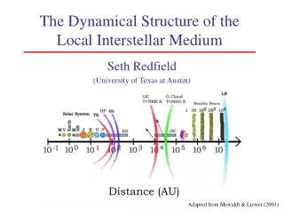
PROPAGATION OF MAGNETARS THROUGH THE INTERSTELLAR MEDIUM. Olga Toropina, Space Research Institute, Moscow, Russia [In collaboration with Marina Romanova & Richard Lovelace] [Department of Astronomy, Cornell University, USA]. I. INTRODUCTION - NEUTRON STARS EVOLUTION STAGES.

E N D
PROPAGATION OF MAGNETARS THROUGH THE INTERSTELLAR MEDIUM Olga Toropina, Space Research Institute, Moscow, Russia [In collaboration with Marina Romanova & Richard Lovelace] [Department of Astronomy, Cornell University, USA]
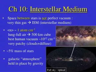
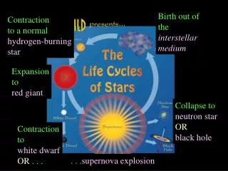
I. INTRODUCTION - NEUTRON STARS EVOLUTION STAGES Rotating magnetized neutron stars pass through different stages in their evolution: Ejector – a rapidly rotating (P<1s) magnetized neutron star is active as a radiopulsar. The NSspins down owing to the wind of magnetic field and relativistic particles from the region of the light cylinder RL(RA > RL). Propeller – after the NSspins-down sufficiently, the relativistic wind is then suppressed by the inflowing matter RL> RA. Until RC<RA, the centrifugal force prevents accretion, NS rejects an incoming matter (RC<RA< RL). Accretor– NS rotates slowly,matter can accrete onto star surface(RA < RC , RA < RL). Georotator– NSmoves fast through the interstellar medium(RA > Rасс). • Alfven radius(magnetospheric radius):rV2/2 = B2/8p • RA=2 x 1012cm, , B=1015 G, V=100 км/с, n=1 cm-3 • Accretionradius:Rасс = 2GM* / (cs2 + v2)=4 x 10¹³ M/v1002 • Corotation radius:RC =(GM/W2)1/3= 2 x 10⁸ P12/3 cm • Light cylinderradius: RL=cP/2p = 5 x 10⁹ P1 cm
I. INTRODUCTION - NEUTRON STARS EVOLUTION STAGES Some neutron stars with anomalously strong magnetic field B ~ 1014 – 1016 G are called Magnetars (Duncan & Thompson 1992, 1995) There is suggestion (based on observations) that soft gamma-ray repeaters (SGRs) and long-period pulsars in supernova remnants are magnetars (Kulkarni & Frail; Kouveliotou et al) The estimated birthrate of SGRs is ~ 10% of ordinary pulsars (Kulkarni & Frail; Kouveliotou et al). Thus, magnetars may constitute a nonnegligible percentage of neutron stars (unless their magnetic field decays rapidly) Magnetars pass through their evolution stages much faster than classical pulsars.
I. INTRODUCTION - NEUTRON STARS EVOLUTION STAGES We investigate the propagation of magnetars through theinterstellar medium (ISM). We consider two cases: (1) Slowrotating magnetar, when Rасс~ RA gravitationalfocusing is important, matter can accrete onto star surface (2) Magnetar is rotating in the propellerregime, when RC < RA rotating star’s magnetic field rejects an incoming matter.
II. MHD SIMULATION OF ACCRETION TO A MAGNETIZED STAR We consider the equation system for resistive MHD (Landau, Lifshitz 1960): 7/5, 5/3 Non-relativistic, axisymmetric resistive MHD code is used. The codeincorporates the methods of local iterations and flux-corrected transport. We assume axisymmetry, but calculate all three components of v and B.We use the vector potential A so that the magnetic field B = x A automatically satisfies •B = 0. We use a cylindrical, inertial coordinate system (r,f,z) with the z-axis parallel to the star's dipole moment m and rotation axis W. The equatorial plane is treated as symmetry plane.
II. GEOMETRY OF THE MHD SIMULATION REGION m - the magnetic moment of the star; W*- the angular velocity of the star; R*- the radius of the star, Rmax, Zmax - the limits of the computational region: R* << Rmax The size of the region was taken to be less then the sonic radius of the Bondi flow Rs=[(5-3g)/4]RB, thus matter inflows supersonically to the computational region. The inflow rate is taken to be the Bondi accretion rate: MBondi= 4p l (GM*)2 r/c3, where l =0.625 for g=7/5. The incoming matter is assumed to be unmagnetized. A uniform (r,z) grid with 513 x 513 cells was used. . There is only one analytical solution for spherical accretion onto non-magnetic center – Bondi 1952. We use this Bondi solution as a boundary condition. In simulations of accretion to an unmagnetized star, we observed that matter accretes supersonically at the Bondi rate. The velocity and density variations were those of the Bondi solution, and no discontinuities were observed in the simulation region.
II. GEOMETRY OF THE MHD SIMULATION REGION . We use a cylindrical inertial coordinate system (r,f, z), with origin at the star’s center. Z-axis is parallel to the velocity of the ISM at large distances. The dipole magnetic moment of the star m is parallel or antiparallelto the z-axis. Supersonic inflow with Mach number M . The incoming matter is assumed to be unmagnetized. g = 5/3
III. ACCRETION ONTO SLOW ROTATING AND SLOW MOVING STAR 1. THE STRUCTURE OF THE ACCRETION FLOW Two distinct regions separated by a shock wave are observed. One is the external region where matter inflows with the Bondi rate and the density and velocity agree well with the Bondi (1952) solution. The second is the internal region, where the flow is strongly influenced by the stellar magnetic field. The background scale represents the density of the flow and the solid lines the poloidal magnetic field lines. The length of the arrows is proportional to flow speed. The thick solid line shows the Alfve´n surface. The dashed line shows the sonic surface. The flow becomes strongly anisotropic close to the dipole.
III. ACCRETION ONTO SLOW ROTATING STAR AND SLOW MOVING STAR 2. THE STRUCTURE OF THE ACCRETION FLOW INSIDE OF MAGNETOSPHERE The anisotropyof the flow is evident. The plasma flows along the magnetic field lines to form polaraccretion columns. The density in the accretion columns is3–4 orders of magnitude larger than that in the equatorialplane. The background scale represents the density of the flow and the solid lines the poloidal magnetic field lines. The thick solid line shows the Alfveґn surface.
III. ACCRETION ONTO SLOW ROTATING STAR AND SLOW MOVING STAR 3. TWO DISTINCT REGIONS SEPARATED BY A SHOCK WAVE Mass accretion rate through the spheres of radii R at time t=1.7tff . R* is the radius of the star and Rsh is the equatorial radius of the shock. One can see two regions separated by the shock wave with different accretion rate. Inside shock wave the accretion rate is smaller than MBondi and approximately constant out to the radius of the shock (Rsh), which is propagating outward. This means that a new matter flow has been established around the magnetized star and that it is stationary. At the shock wave R = Rsh, the accretion rate jumps up to the Bondi rate.
III. ACCRETION ONTO SLOW ROTATING STAR AND SLOW MOVING STAR 5. DEPENDENCE OF THE ACCRETION RATE ON MAGNETIC FIELD OF THE STAR Dependence of the accretion rateon the magnetic moment~ m -3 Differential mass accretion rate per unit solid angle dM/dWas a function of the polar angle Q for different magnetic moments m at aradius 2R*. The dashed line corresponds to Bondi accretion onto a nonmagnetizedstar.
IV. ACCRETION ONTO SLOW ROTATING AND MOVING STAR, (RA < Racc) Gravitationalfocusing is important. Magnetic field of the star acts as anobstacle for the flow; a conical shock wave forms. Results of simulations of accretion to a magnetized star with magnetic field at Mach numberM = 3 andg = 5/3. Poloidal magnetic B field lines andvelocity vectors are shown. The background represents logarithm of density. The thick line represents the Alfven surface.
IV. ACCRETION ONTO SLOW ROTATING AND MOVING STAR, (RA < Racc) DENSITY, VELOSITY AND ENERGY DISTRIBUTION
IV. ACCRETION ONTO SLOW ROTATING AND MOVING STAR, (RA ~ Racc) Gravitationalfocusing is less important. Magnetic field of the star acts as anobstacle for the flow; a conical shock wave forms. Results of simulations of accretion to a magnetized star with magnetic field at Mach numberM = 3 andg = 5/3. Poloidal magnetic B field lines andvelocity vectors are shown. The background represents logarithm of density. The thick line represents the Alfven surface.
IV. ACCRETION ONTO SLOW ROTATING AND MOVING STAR, (RA ~ Racc) ENERGY DISTRIBUTION IN MAGNETOTAIL
IV. ACCRETION ONTO SLOW ROTATING AND MOVING STAR, (RA ~ Racc) DEPENDENCE OF THE ACCRETION RATE ON MAGNETIC FIELD OF THE STAR Dependence of the accretion rateon the magnetic moment for M=3, normalized toMBHL.
IV. ACCRETION ONTO SLOW ROTATING AND FAST MOVING STAR, (RA > Racc) Gravitationalfocusing is not important. Magnetic field of the star acts as anobstacle for the flow; but bow shock is narrow.Magnetic lines form long magnetotail. Results of simulations of accretion to a magnetized star with magnetic field at Mach numberM = 10 andg = 5/3. Poloidal magnetic B field lines andvelocity vectors are shown. The background represents logarithm of density. The thick line represents the Alfven surface.
IV. ACCRETION ONTO SLOW ROTATING AND FAST MOVING STAR, (RA > Racc) DENSITY AND MAGNETIC FIELD VARIATIONS AT DIFFERENT MACH NUMBERS • Density in the magnetotail is low • Magnetic fieldin the magnetotail reduced gradually
V. SPHERICAL ACCRETION ONTO STARIN THE PROPELLER REGIME 1. THE STRUCTURE OF THE ACCRETION FLOW Matter flow in the "propeller" regime for a star rotating at W*=0.5 WK* after 7 rotation periods of the star.The axes are measured in units of the star's radius. The background represents the density and the length of the arrows is proportional to the poloidal velocity. The thin solid lines are magnetic field lines. Two distinct regions separated by a shock wave are observed. One is the external region where matter inflows with the Bondi rate and the density and velocity agree well with the Bondi (1952) solution. The second is the internal region, where the flow is strongly influenced by the stellar magnetic field and rotation.
V. SPHERICAL ACCRETION ONTO STARIN THE PROPELLER REGIME 2. THE STRUCTURE OF THE ACCRETION FLOW INSIDE OF MAGNETOSPHERE Spherical accretion to a rapidly rotating star. Matter flow in the "propeller" regime for a star rotating at W*=0.5 WK* A new regime of matter flow inside the expanding shock wave. The axes are measured in units of the star's radius. The background represents the density and the length of the arrows is proportional to the poloidal velocity. The thin solid lines are magnetic field lines. The bold line represents the Alfven surface. Dotted line shows sonic surface.
V. SPHERICAL ACCRETION ONTO STARIN THE PROPELLER REGIME 2. THE STRUCTURE OF THE ACCRETION FLOW INSIDE OF MAGNETOSPHERE Matter flow in the "propeller" regime for a star rotating at W*=0.5 WK* . The background represents angular velocity W*= vf (r,z)/r. The axes are measured in units of the star's radius. A new regime of matter flow forms inside the expanding shock wave. The rapidly rotating magnetosphere expels matter outward in the equatorial region.
V. SPHERICAL ACCRETION ONTO STARIN THE PROPELLER REGIME 2. THE STRUCTURE OF THE ACCRETION FLOW INSIDE OF MAGNETOSPHERE A new regime of matter flow inside the expanding shock wave. Figure shows the streamlines of the matter flow. Matter free-falls along the field lines going into the poles of the star. Some matter that flows close to the z-axis accretes onto the surface of the star. However, matter more remote from the z-axis comes close to the star, is deflected by the rotating magnetic field, and then moves outward in the equatorial plane.
THE STRUCTURE OF THE ACCRETION FLOWFOR A STAR ROTATING ATW*=0.5 WK*
VI. ACCRETION ONTO MOVING STARIN THE PROPELLER REGIME 1. THE STRUCTURE OF THE ACCRETION FLOW FOR MOVING STAR AT M=1 289 x 865 g = 5/3 The structure of flow depends on velocity of moving star v. Example of matter flow for a star rotating at W*=0.7 WK and Mach numberM=v/cs=1. Accretion radius Rасс=2GM* / (cs2 + v2) is large then magnetospheric radius RA. A star can capture a matter, the flow looks like in the spherical case with equatorial outflows. Velocities of star v and outflow vp are the same order, the bow shock is wide. The axes are measured in units of Bondi radius. The background represents the density and the length of the arrows is proportional to the poloidal velocity.
VI. ACCRETION ONTO MOVING STARIN THE PROPELLER REGIME 1. THE STRUCTURE OF THE ACCRETION FLOW FOR MOVING STAR AT M=1 289 x 865, g = 5/3
V. ACCRETION ONTO MOVING STARIN THE PROPELLER REGIME 2. THE STRUCTURE OF THE ACCRETION FLOW FOR FAST MOVING STAR, M=3 289 x 865 g = 5/3 Example of matter flow for a star rotating at W*=0.7 WK and Mach number M=3. Rасс ~ RA The magnetic field ofthe star acts as an obstacle for the flow, most of the inflowingmatter is kept away from the star and a conical shock wave forms. At larger distances the field is stretched by the flow, forming long magnetotail. The rapidly rotating magnetosphere expels matter outward in the equatorial region. This matter first flows radially outward, then along Z-direction.
V. ACCRETION ONTO MOVING STARIN THE PROPELLER REGIME 2. THE STRUCTURE OF THE ACCRETION FLOW FOR FAST MOVING STAR, M=3 289 x 865, g = 5/3
V. ACCRETION ONTO MOVING STARIN THE PROPELLER REGIME 3. AN ANGULAR MOMENTUM FLUX Rapidly rotating star looses an angular momentum and spins down. We can estimate the total angular momentum loss rate from the star by evaluating the integral over the surface around the star's magnetosphere: Left panel: Angular momentum flow connected with matter. Right panel: Angular momentum flow connected with magnetic field.
V. ACCRETION ONTO MOVING STARIN THE PROPELLER REGIME 4. AN ANGULAR MOMENTUM EVOLUTION The total angular momentum flux around the magnetosphere (solid line) becomes constant approximately after 10-15 rotation periods of the star. As the matter is passing the angular momentum flux in tail (dotted line) is increasing up to value of flux around the magnetosphere and becomes constant. Figure shows that total flux across section z=0.6 becomes constant and equal to flux around the magnetosphere approximately after 26 rotation periods.
V. ACCRETION ONTO MOVING STARIN THE PROPELLER REGIME DEPENDENCE OF THE ANGULAR MOMENTUM FLUX ON DIFFERENT PARAMETERS The summary of scaling laws:
V. ACCRETION ONTO MOVING STARIN THE PROPELLER REGIME 5. SPIN-DOWN OF MAGNETARS We can estimate spin-down of magnetar due to the propeller effect for typically parameters: M = 1.4 M☼= 2.8 x 1033 g, R = 106 km, B = 1015 Gs, P = 105 s, n∞ = 1 cm-3, cs = 30 km/s. The characteristic time of spin-down is DT= L*/L, where L*=I*W*- an angular momentum of a star L - an angular momentum loss rate, which is obtained by evaluating the integral: . . .
V. ACCRETION ONTO MOVING STARIN THE PROPELLER REGIME 5. SPIN-DOWN OF MAGNETARS The characteristic time of spin-down is For periods P*~ 103 s, which correspond tobeginning of the propeller stage, the evolution scale will beDT = 103 years, while at period P*~ 106 scorrespondingto the end of propeller stage DT = 3 x10⁴ years. Thus wesee that magnetars are expected to spin down very fast atthe propeller stage. This time-scale however may be muchlarger if diffusivity is very small.